
Method and device for cutting off a thick-walled pipe

a technology of thick-walled pipes and cutting tools, which is applied in the direction of metal sawing devices, metal sawing equipment, turning equipment, etc., can solve the problems of large blade acquisition costs, material losses, and the inability to remove a sizable chip from the first wall, so as to improve the feed rate of the sawing unit, reduce the risk of blade breaking, and facilitate the effect of implementation

Inactive Publication Date: 2010-08-03
PLANTOOL
View PDF11 Cites 3 Cited by
  • Summary
  • Abstract
  • Description
  • Claims
  • Application Information

AI Technical Summary

Benefits of technology

The method reduces material loss, lowers equipment costs, and decreases the risk of blade breakage, while allowing for more efficient cutting with potentially fewer blades, and adjustable power usage during different stages of cutting.

Problems solved by technology

A greater thickness of the blade causes material losses.
Furthermore, it is expensive to acquire big blades.
If a thick-walled pipe is cut off, a problem arises that a sizable chip removed from the first wall will not necessarily be detached from the throat of the blade before it touches the wall a second time during the same blade revolution.
This makes the cutting less effective and may result in breaking of the blade.

Method used


Image

  • Method and device for cutting off a thick-walled pipe
  • Method and device for cutting off a thick-walled pipe
  • Method and device for cutting off a thick-walled pipe

Examples


Embodiment Construction

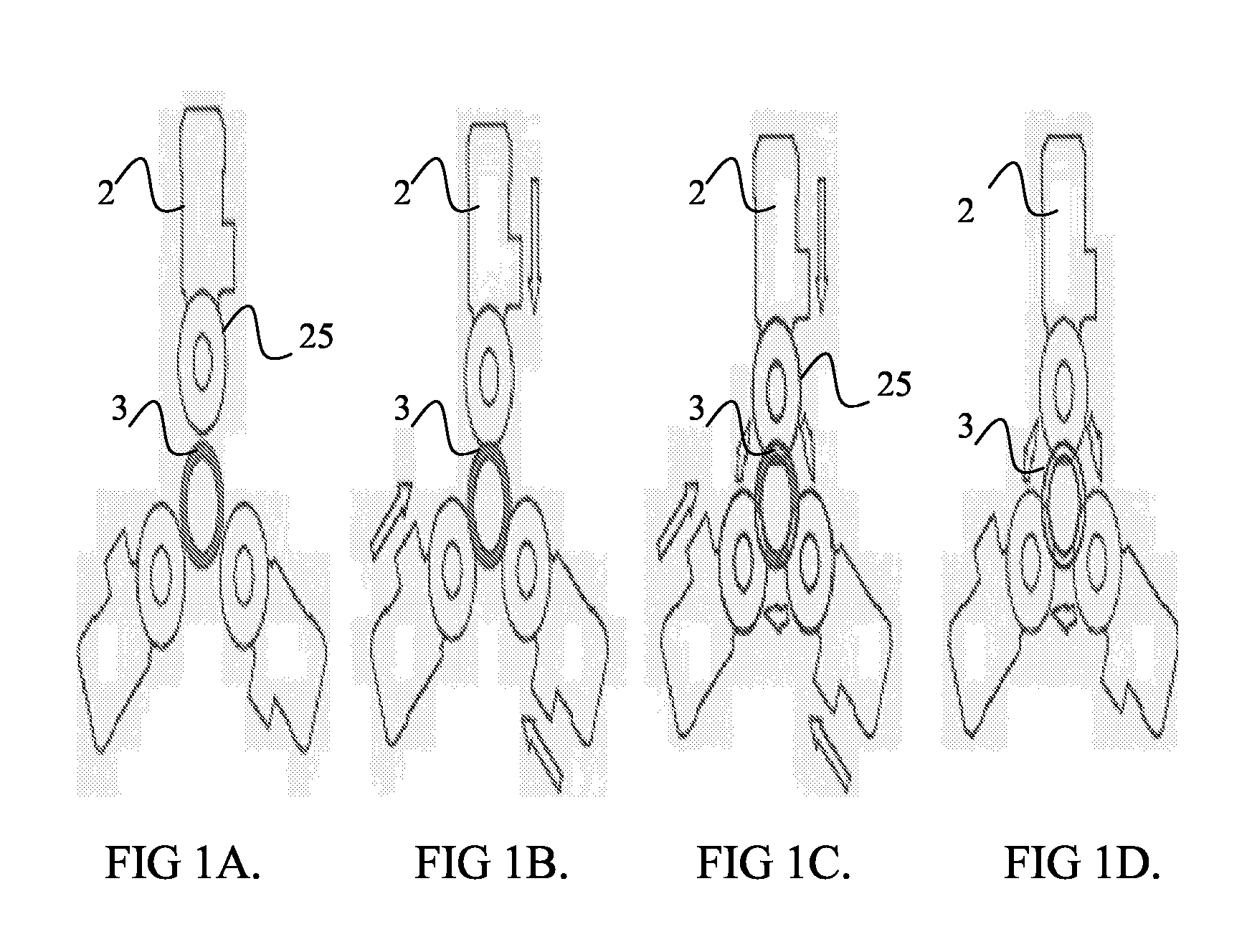
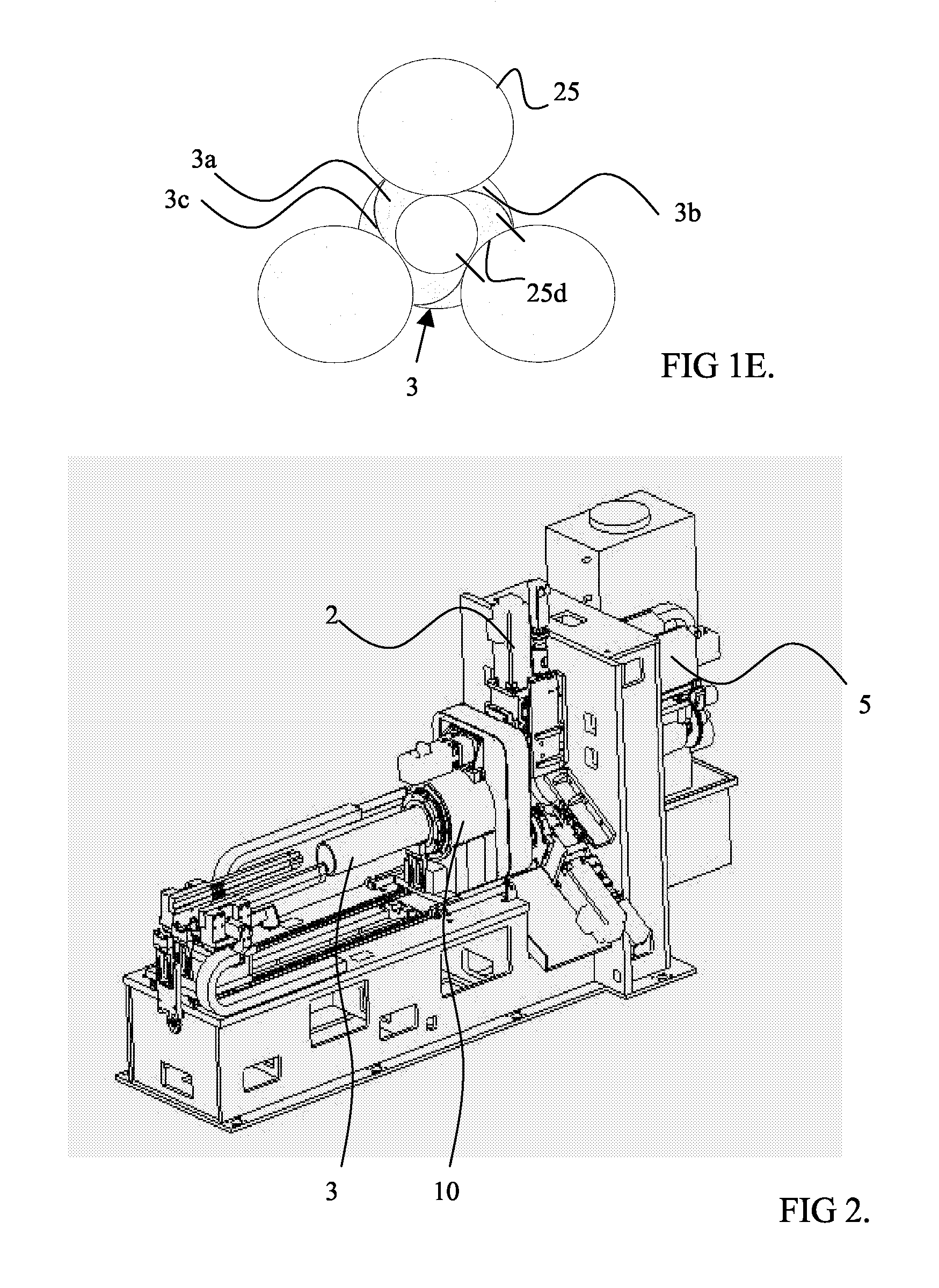
[0026]A reference is made to FIGS. 1A to 1D, which illustrate four stages according to the method. FIGS. 1A to 1D show an embodiment comprising three saws. FIG. 1A shows the initial state, in which the cut-off point of a pipe 3 is brought to a location where it is cut and saws 2 may be started. Before the cutting the pipe 3 is locked in its place. FIG. 1B illustrates the stage at which three saw blades 25 are driven radially towards the centre of the pipe. In FIG. 1C, the inner arrows illustrate the rotating of the pipe 3. The rotating of the pipe is started before the saw blades 25 pass through the inner surface of the pipe. Also, the rotating of the pipe may be started before or immediately after the saws of the sawing units have touched the outer circumference of the pipe 3. From FIG. 1D it appears that the radial driving of the blades 25 towards the centre of the pipe has been stopped after the cutting blade 25 has passed through the inner wall of the pipe 3. The rotating of the...


PUM

PropertyMeasurementUnit
thicknessaaaaaaaaaa
outer diametersaaaaaaaaaa

Abstract

The invention relates to a method for cutting off a thick-walled pipe 3, wherein the pipe to be cut comprises an inner circumference closer to the longitudinal axis of the pipe and an outer circumference further from the longitudinal axis of the pipe. The method comprises bringing the cut-off point of the pipe to the cut-off point of a sawing unit, locking the pipe in its place by means of a fastener, sawing the pipe at the cut-off point by moving a saw 2 of the sawing unit towards the center of the pipe 3, the sawing unit comprising at least two saws. The method is characterized by moving each saw 2 of the sawing unit during the sawing radially towards the centre of the pipe until the saw blades pass through the inner surface of the pipe, and rotating the pipe during the sawing with respect to its longitudinal axis by means of a rotating device 10 connected to the fastener until the pipe is cut off, whereby, due to the rotating of the pipe, the blades 25 of the saw 2 work the pipe during a blade revolution only in one direction, which is directed from the outer circumference towards the inner circumference. Furthermore, the invention provides a saw assembly and a rotating device for implementing the method.

Description

[0001]This application is a U.S. National Phase of International Patent Application Ser. No. PCT / FI2005 / 050350, filed Oct. 7, 2005 which claims priority to Finnish Patent Application No. 20045377 filed Oct. 8, 2004.BACKGROUND OF THE INVENTION[0002]The invention relates to a method and device for cutting off a thick-walled pipe. In this description a thick-walled pipe refers to a pipe with a wall thickness of approximately 10 to 50 mm. The outer diameters of such pipes may vary between 80 and 400 mm, for instance.[0003]According to the prior art, a pipe is cut off by a single-blade saw. In single-blade cutting, the diameter of the blade should be larger than the diameter of the pipe to be cut. Also, the thickness of the blade with a large diameter is great and the structure of the saw is sufficiently firm to use the blade with a large diameter. A greater thickness of the blade causes material losses. Furthermore, it is expensive to acquire big blades.[0004]Patent publication GB 88459...

Claims


Application Information

Patent Timeline
Patent Type & Authority Patents(United States)
IPC IPC(8): B23B31/16B23B5/12B23DB23D45/10B23D45/12
CPCB23D45/105B23D47/04B23D45/124Y10T82/10Y10T83/7755Y10T83/0596B23D45/10
Inventor RANTALA, JARISALMINEN, KEIJO
Owner PLANTOOL
Learn More