Monitoring of a flame existence and a flame temperature

a technology of flame existence and temperature, applied in the direction of burner control devices, instruments, optical radiation measurement, etc., can solve the problem that comparable devices using thermocouples are likely to fail due to their fragility

Inactive Publication Date: 2010-08-03
SIEMENS AG
View PDF21 Cites 10 Cited by
  • Summary
  • Abstract
  • Description
  • Claims
  • Application Information

AI Technical Summary

Benefits of technology

[0004]It is an objective of the present invention to provide a method for monitoring a flame in a combustion area like, e.g., a combustion chamber. It is a further objective of the present invention to provide a burner which allows the monitoring of a flame in a combustion zone. It is another objective of the present invention to provide a gas turbine comprising a burner which allows the flame to be monitored. It is a still further objective of the present invention to provide an internal combustion engine which allows the monitoring of a temperature in a cylinder.

Problems solved by technology

Comparable devices using thermocouples would be likely to fail due to their fragility.

Method used


Image

  • Monitoring of a flame existence and a flame temperature
  • Monitoring of a flame existence and a flame temperature
  • Monitoring of a flame existence and a flame temperature

Examples


Embodiment Construction

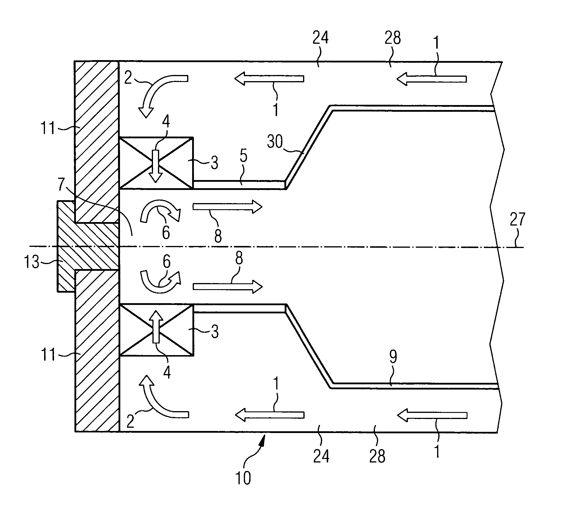
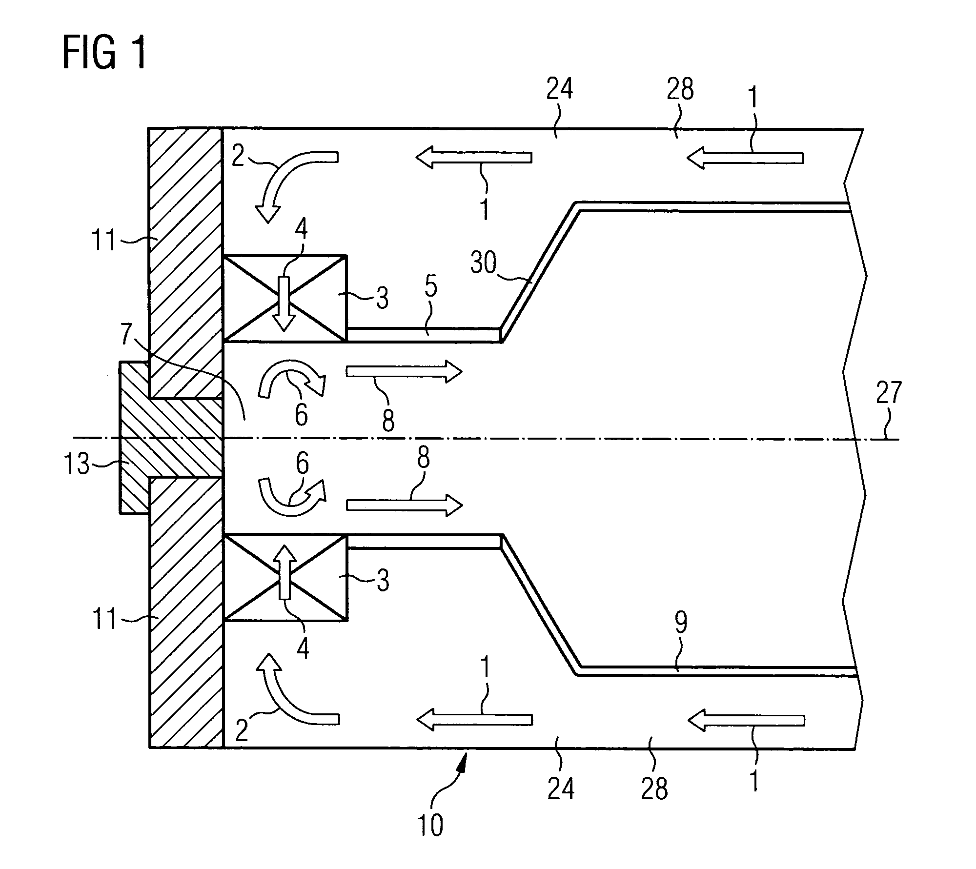
[0030]An embodiment of the present invention will now be described with reference to FIGS. 1 to 6. FIG. 1 schematically shows a part of a combustor of a gas turbine engine in a sectional view.

[0031]The combustor comprises in flow series a burner with a swirler portion 3 and a burner-head portion 11 attached to the swirler portion 3, a transition piece being referred as combustion pre-chamber 5 and a main combustion chamber 9. The main combustion chamber 9 has a diameter being larger than the diameter of the pre-chamber 5. The main combustion chamber 9 is connected to the pre-chamber 5 via a dome portion 30. In general, the transition piece 5 may be implemented as a one part continuation of the burner towards the main combustion chamber 9, as a one part continuation of the main combustion chamber 9 towards the burner, or as a separate part between the burner and the main combustion chamber 9.

[0032]The burner comprises a radial swirler 3 and a head plate 11 to which the swirler 3 is f...


PUM


Abstract

A method for monitoring a flame in a combustion chamber comprising a wall with an outer side is provided, wherein the radiation which is emitted from a part of the outer side of the wall is optically detected by a sensor. Furthermore, a burner is provided, especially for use in a gas turbine. The burner comprises a wall section with an inner side, which shows towards a combustion zone, and an outer side. The burner further comprises a sensor for optically detecting the radiation emitted from the outer side of said wall section.

Description

CROSS REFERENCE TO RELATED APPLICATIONS[0001]This application claims the benefits of British application No. 07016386.0 filed Aug. 21, 2007 and is incorporated by reference herein in its entirety.FIELD OF INVENTION[0002]The present invention relates to a device and a method for monitoring a flame in a combustion chamber. Especially, it relates to a temperature measurement arrangement for use in a burner of a gas turbine engine.BACKGROUND OF THE INVENTION[0003]A gas turbine engine usually comprises a compressor, a combustion chamber and a turbine. The compressor delivers compressed air for use in the combustion chamber. In the combustion chamber a mixture of air and fuel is combusted by means of a burner in order to produce a hot gas stream which drives the turbine. Typically one or more burners are used. In this context it is important to monitor the flame to avoid instabilities of the combustion process. Therefore, it is desired to detect the presence of the flame and the intensity...

Claims


Application Information

Patent Timeline
Patent Type & Authority Patents(United States)
IPC IPC(8): G01M15/14
CPCF02B77/085F02B77/089F23N5/082F02D35/022F23D2208/10F23N2029/00F23N2900/05005F23N2229/00
Inventor WILBRAHAM, NIGEL
Owner SIEMENS AG
Why Eureka
Try Eureka