System and method for providing a high input common mode current conveyor

a high-input, common-mode technology, applied in the direction of amplifiers, instruments, amplifiers with semiconductor devices/discharge tubes, etc., can solve the problems of increasing the voltage at the “acgnd”, causing noise for the transmitter, loss of gain in the current conveyor b>, etc., to achieve a greater tolerance of noise

Active Publication Date: 2010-07-27
NAT SEMICON CORP
View PDF5 Cites 5 Cited by
  • Summary
  • Abstract
  • Description
  • Claims
  • Application Information

AI Technical Summary

Benefits of technology

[0016]The operation of the current conveyer circuit of the invention effectively increases the range of the common mode voltage of the receiver without adversely affecting the functionality of the receiver. The NMOS transistor and the PMOS transistor are kept in saturation during operation of the mobile pixel link (MPL) receiver. As will be more fully described, this is accomplished by keeping the gate to source voltage of the NMOS transistor less than or equal to the threshold voltage of the PMOS transistor.
[0018]It is also an object of the present invention to provide a system and method for providing an improved current conveyor circuit in a mobile pixel link (MPL) receiver that can provide an increased input common mode voltage to allow a greater tolerance of noise on an MPL transmission line.
[0019]It is yet another object of the invention to provide a system and method for providing an improved current conveyor circuit in a mobile pixel link (MPL) receiver that can effectively increase the range of an input common mode voltage of the MPL receiver without adversely affecting the functionality of the MPL receiver.

Problems solved by technology

The low common mode voltage of prior art MPL receiver 100 can create problems for a transmitter in the presence of noise.
This will cause a loss of gain in current conveyor 120.
In that case, increasing the voltage at the “acgnd” node would create either (1) a loss of gain, or (2) an increase in current consumption.

Method used


Image

  • System and method for providing a high input common mode current conveyor
  • System and method for providing a high input common mode current conveyor
  • System and method for providing a high input common mode current conveyor

Examples


Embodiment Construction

[0027]FIGS. 2 through 4, discussed below, and the various embodiments used to describe the principles of the present invention in this patent document are by way of illustration only and should not be construed in any way to limit the scope of the invention. Those skilled in the art will understand that the principles of the present invention may be implemented in any type of suitably arranged high input common mode mobile pixel link (MPL) receiver.

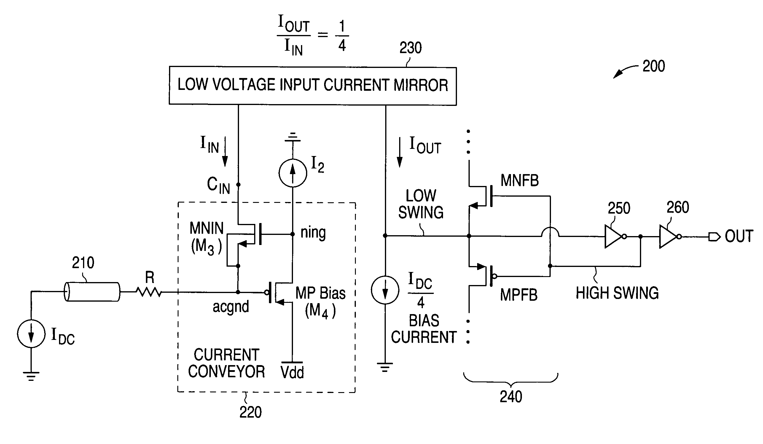
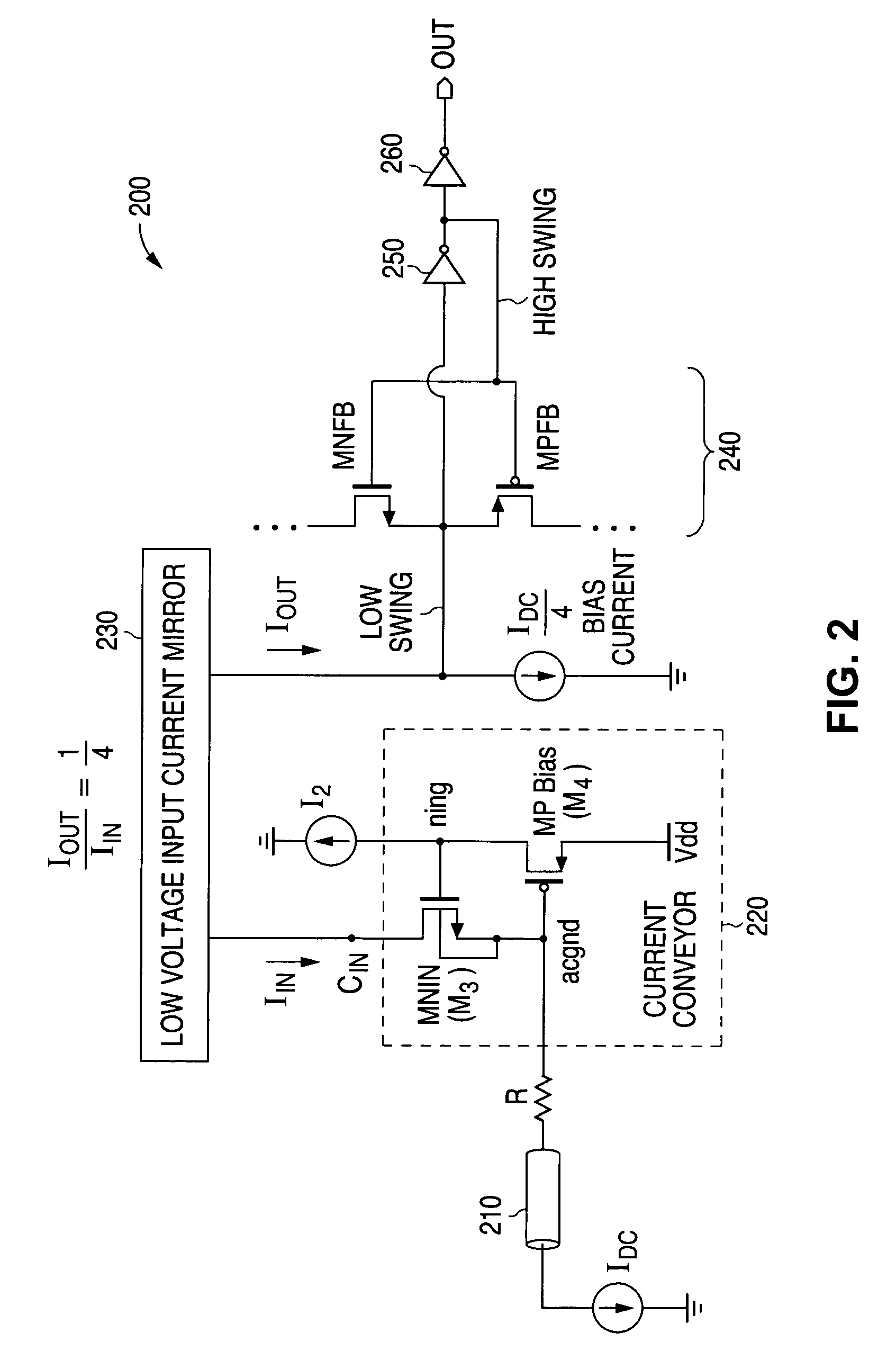
[0028]FIG. 2 is a block diagram illustrating a high common mode input mobile pixel link (MPL) receiver 200 of the present invention with a current conveyor circuit 220 of the present invention. A transmitter represented by current source IDC provides a data signal through transmission line 210 to current conveyor 220 of receiver 200. The output of transmission line 210 is coupled to a first end of matching resistor R. In one commonly encountered embodiment transmission line 210 has an impedance of fifty ohms (50Ω) and matching resistor R ...


PUM


Abstract

A system and method is disclosed for providing an improved current conveyor circuit in a mobile pixel link (MPL) receiver that can provide an increased input common mode voltage to allow a greater tolerance of noise on a transmission line. The current conveyor circuit comprises (1) a PMOS transistor with a source coupled to an operating voltage Vdd and a drain that is coupled to a current source, and (2) an NMOS transistor with a source coupled to an input terminal of the current conveyor circuit and a drain coupled to a low voltage input current mirror. The current conveyer circuit increases the range of the common mode voltage of the receiver without adversely affecting the functionality of the receiver.

Description

TECHNICAL FIELD OF THE INVENTION[0001]The present invention relates generally to integrated circuits and, more particularly, to a system and method for providing a high input common mode current conveyor.BACKGROUND OF THE INVENTION[0002]A major goal in the design and manufacture of electronic circuitry is to increase the accuracy, precision and capability of wireless handheld devices such as cellular phones. The newer types of cellular phones incorporate digital cameras and data service features. These features require the presence of high density, high color display modules. This means that there is an increasing need for wide, high-speed parallel interfaces to interconnect between baseband processors, application processors, image processors and the input / output (I / O) devices that they support (such as digital cameras and display modules).[0003]One type of interface used in such devices is referred to as a Mobile Pixel Link (MPL). The MPL interface uses a very low power, low elect...

Claims


Application Information

Patent Timeline
Patent Type & Authority Patents(United States)
IPC IPC(8): G05F1/10G05F3/02
CPCG05F3/262H03F3/345H03F3/347H03F2200/91
Inventor FISH, ADAM NICHOLAS
Owner NAT SEMICON CORP
Why Eureka
Try Eureka