Stator support structure for a torque converter
a technology of torque converter and support structure, which is applied in the direction of rotary clutches, fluid couplings, gearings, etc., can solve the problems of increasing the cost of the outer race, and difficulty in performing the ordinarily easy task
- Summary
- Abstract
- Description
- Claims
- Application Information
AI Technical Summary
Benefits of technology
Problems solved by technology
Method used
Image
Examples
Embodiment Construction
[0020]Example embodiments of the present invention are described below, with reference made to the accompanying drawings.
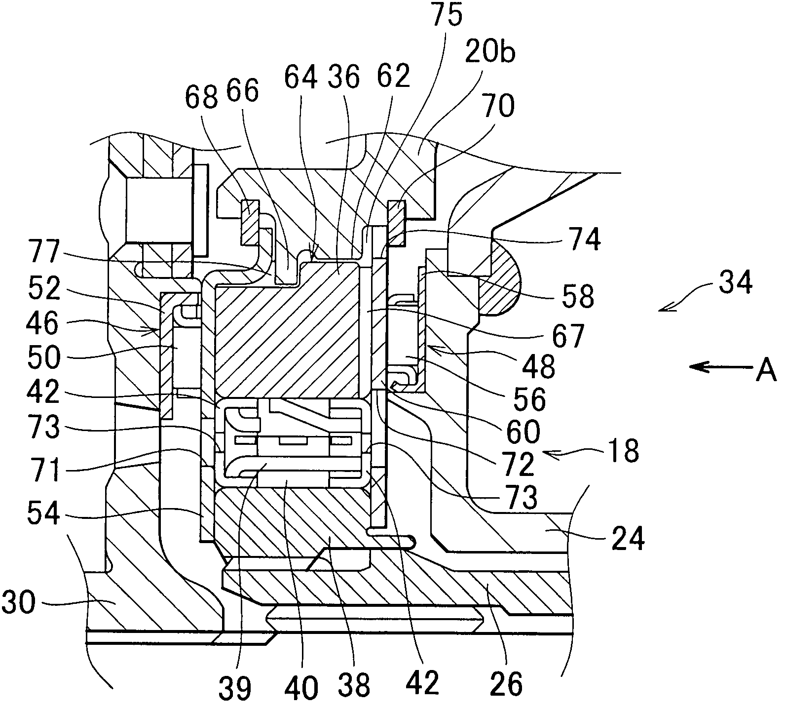
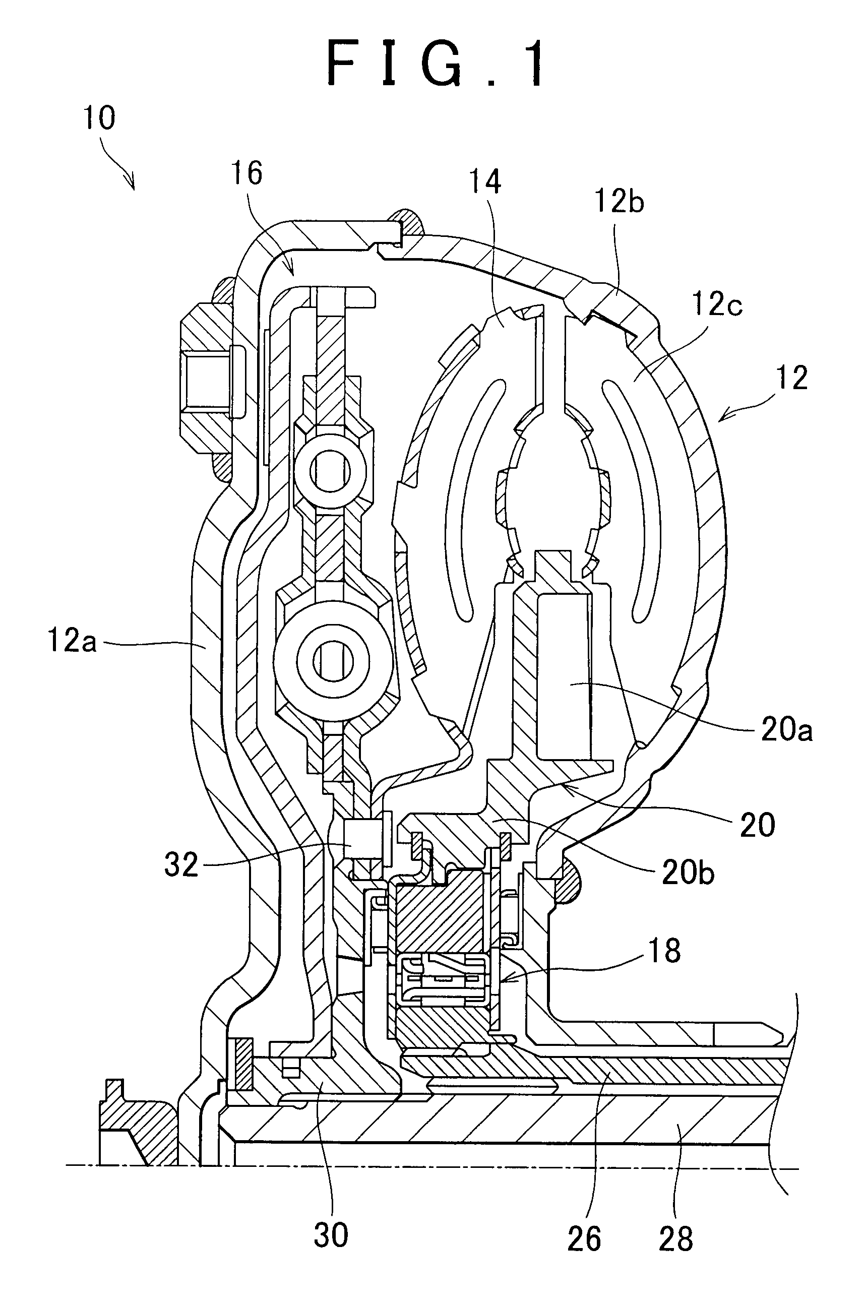
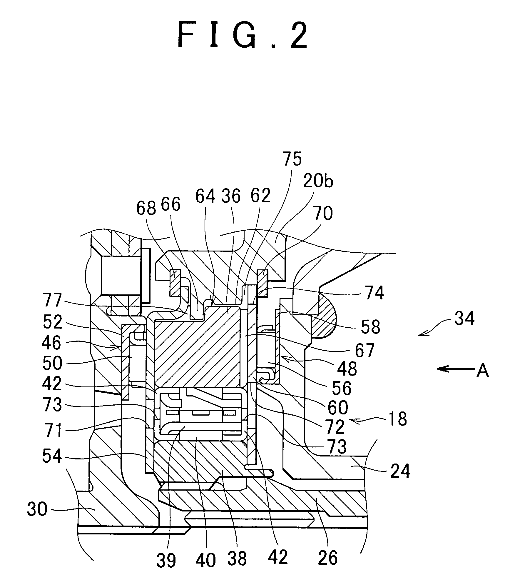
[0021]FIG. 1 is a cross-sectional view showing the configuration of a torque converter 10 according to an embodiment of the present invention. The torque converter 10 has a pump impeller 12, a turbine runner 14, a lock-up clutch 16, a one-way clutch 18, and a stator 20.
[0022]The pump impeller 12, for example, has a front case 12a, a rear case 12b, and an impeller wheel 12c. The front case 12a and the rear case 12b are linked to the crankshaft, to which the output of the engine (not illustrated) is transmitted, and are caused to rotate about their axes at the same rotational speed as the crankshaft. The impeller wheel 12c, having a plurality of blades, is provided around the circumference of the rear case 12b. When the engine rotates the front case 12a, the impeller wheel 12c of the pump impeller 12 is caused to rotate in concert with the front case 12a. By the rot...
PUM
 Abstract
Description
Claims
Application Information
 - R&D
- Intellectual Property
- Life Sciences
- Materials
- Tech Scout
- Unparalleled Data Quality
- Higher Quality Content
- 60% Fewer Hallucinations
Browse by: Latest US Patents, China's latest patents, Technical Efficacy Thesaurus, Application Domain, Technology Topic, Popular Technical Reports.
© 2025 PatSnap. All rights reserved.Legal|Privacy policy|Modern Slavery Act Transparency Statement|Sitemap|About US| Contact US: help@patsnap.com


