
High-throughput communication system, communication terminal, session relay, and communication protocol

a communication system and high-throughput technology, applied in the field of high-throughput communication systems, to achieve the effect of improving throughput and high throughpu

Inactive Publication Date: 2010-07-20
NEC CORP +1
View PDF16 Cites 11 Cited by
  • Summary
  • Abstract
  • Description
  • Claims
  • Application Information

AI Technical Summary

Benefits of technology

[0009]It is therefore an object of this invention to provide a communication system that is capable of achieving high throughput simply by protocol processing at a terminal without requiring a mechanism for sending, from a network to a terminal, information about a cause of packet loss and a quality of a radio channel.
[0010]It is another object of this invention to provide a communication system which allows coexistence of a newly-introduced TCP session and an existing TCP session in a single network by fairly sharing a bandwidth between these TCP sessions.
[0011]It is still another object of this invention to provide a terminal and a session relay both of which are effectively used in the communication system.
[0013]With the communication system, the terminals, and the session relay, the following effect is achieved.
[0014]First, high throughput is achieved simply by protocol processing at a terminal without requiring a mechanism for sending, from the network to the terminal, information about a cause of packet loss and a quality of a radio channel. It is easy to introduce a mechanism for improving the throughput.
[0015]Second, upon occurrence of contention between a newly-introduced TCP session and an existing TCP session, a bandwidth is fairly shared therebetween. Therefore, these TCP sessions can coexist in a single network without any problem.

Problems solved by technology

Therefore, it is unnecessary to provide a mechanism for informing, from the network to the terminal, information about a cause of packet loss and a quality of a radio channel.

Method used


Image

  • High-throughput communication system, communication terminal, session relay, and communication protocol
  • High-throughput communication system, communication terminal, session relay, and communication protocol
  • High-throughput communication system, communication terminal, session relay, and communication protocol

Examples


first embodiment

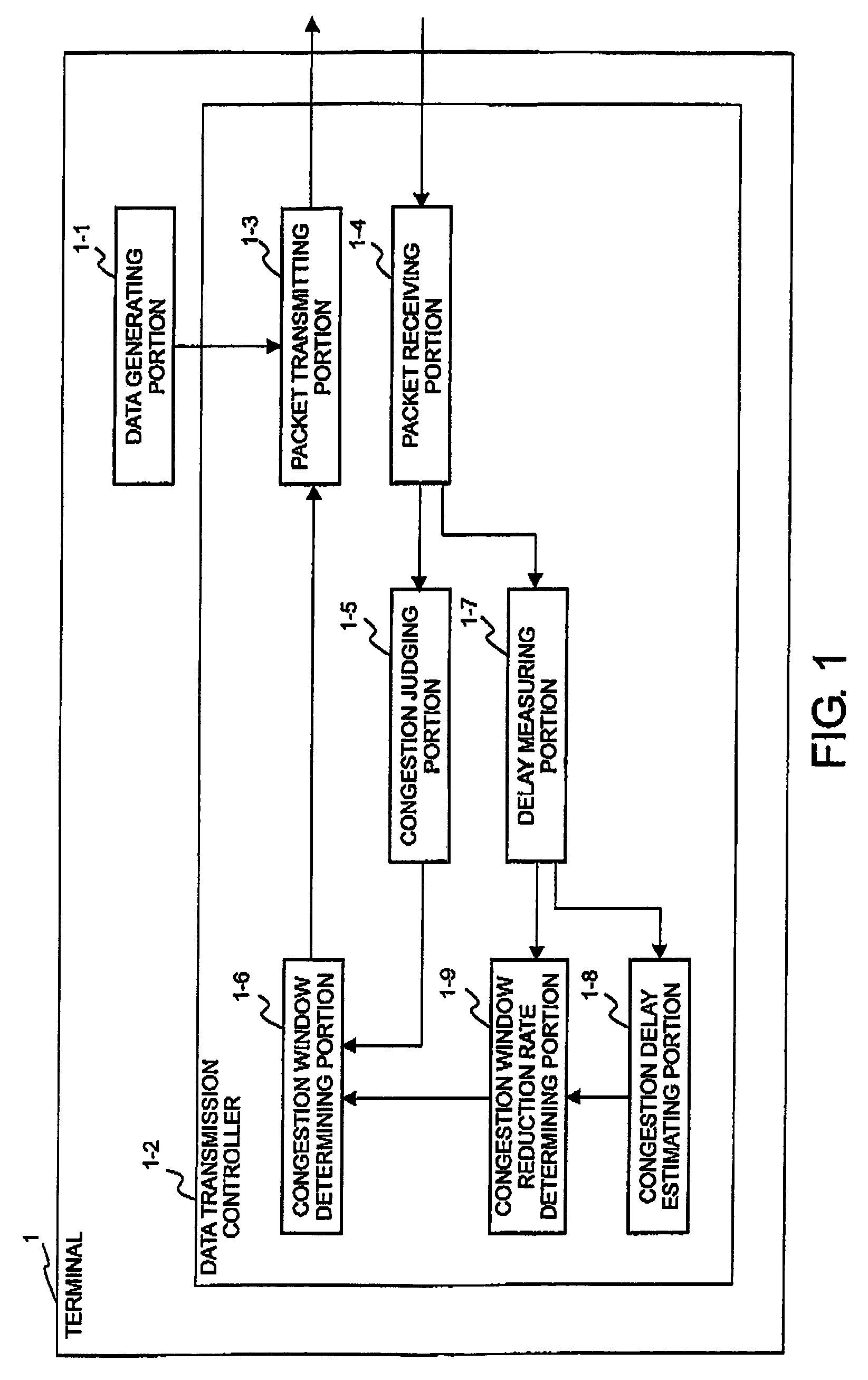
[0023]Referring to FIG. 1, a terminal 1 comprises a data generator 1-1 for generating transmission data and a data transmission controller 12 for delivering the transmission data to a network.

[0024]The data transmission controller 1-2 comprises a packet transmitting portion 1-3 for transmitting packets to the network, a packet receiving portion 1-4 for receiving packets from the network, a congestion judging portion 1-5 for judging occurrence of congestion from presence or absence of packet loss, a congestion window determining portion 1-6 for increasing or decreasing a congestion window, a delay measuring portion 1-7 for measuring a queue delay in the network, a congestion delay estimating portion 1-8 for determining a threshold queue delay at which congestion is to be judged, and a congestion window reduction rate determining portion 1-9 for estimating the possibility that the packet loss is due to congestion and for determining a reduction rate of the congestion window.

[0025]Refe...

second embodiment

[0033]Referring to FIG. 3, a terminal 2 according to a second embodiment of this invention comprises a data generator 2-1 for generating transmission data and a data transmission controller 2-2 for delivering the transmission data to the network.

[0034]The data transmission controller 2-2 comprises, in addition to the structure of the data transmission controller 1-2 of the first embodiment illustrated in FIG. 1, a used bandwidth measuring portion 2-10 for measuring a bandwidth currently used by a TCP session, a channel bandwidth measuring portion 2-11 for measuring a bandwidth of a channel having a smallest bandwidth along a path, and a congestion window increasing rate determining portion 2-12 for increasing the congestion window if the packet loss is detected when the channel or link utilization rate is low. In other words, any other portions 2-3 to 2-9 than 2-10, 2-11, and 2-12 in FIG. 3 are similar in structure and operation to the portions 1-3 to 1-9 illustrated in FIG. 1, resp...

third embodiment

[0044]Referring to FIG. 5, a terminal 3 according to a third embodiment of this invention comprises a date generator 3-1 for generating transmission data and a data transmission controller 3-2 for delivering the transmission data to the network.

[0045]The data transmission controller 3-2 is similar to the data transmission controller 2-2 in the second embodiment except that the delay measuring portion 2-7 is replaced by a delay estimating portion 3-13, although the remaining portions 3-3 to 3-12 are represented by the numerals 2-3 to 2-12 different from FIG. 3, respectively.

[0046]An operation of the third embodiment is different in operation from the second embodiment in the following respect.

[0047]In the second embodiment, the delay measuring portion 2-7 measures the RTT. On the other hand, in the third embodiment, the delay estimating portion 3-13 produces an estimated RTT by the use of an available bandwidth measured by an available bandwidth measuring portion 3-10. Specifically, ...


PUM


Abstract

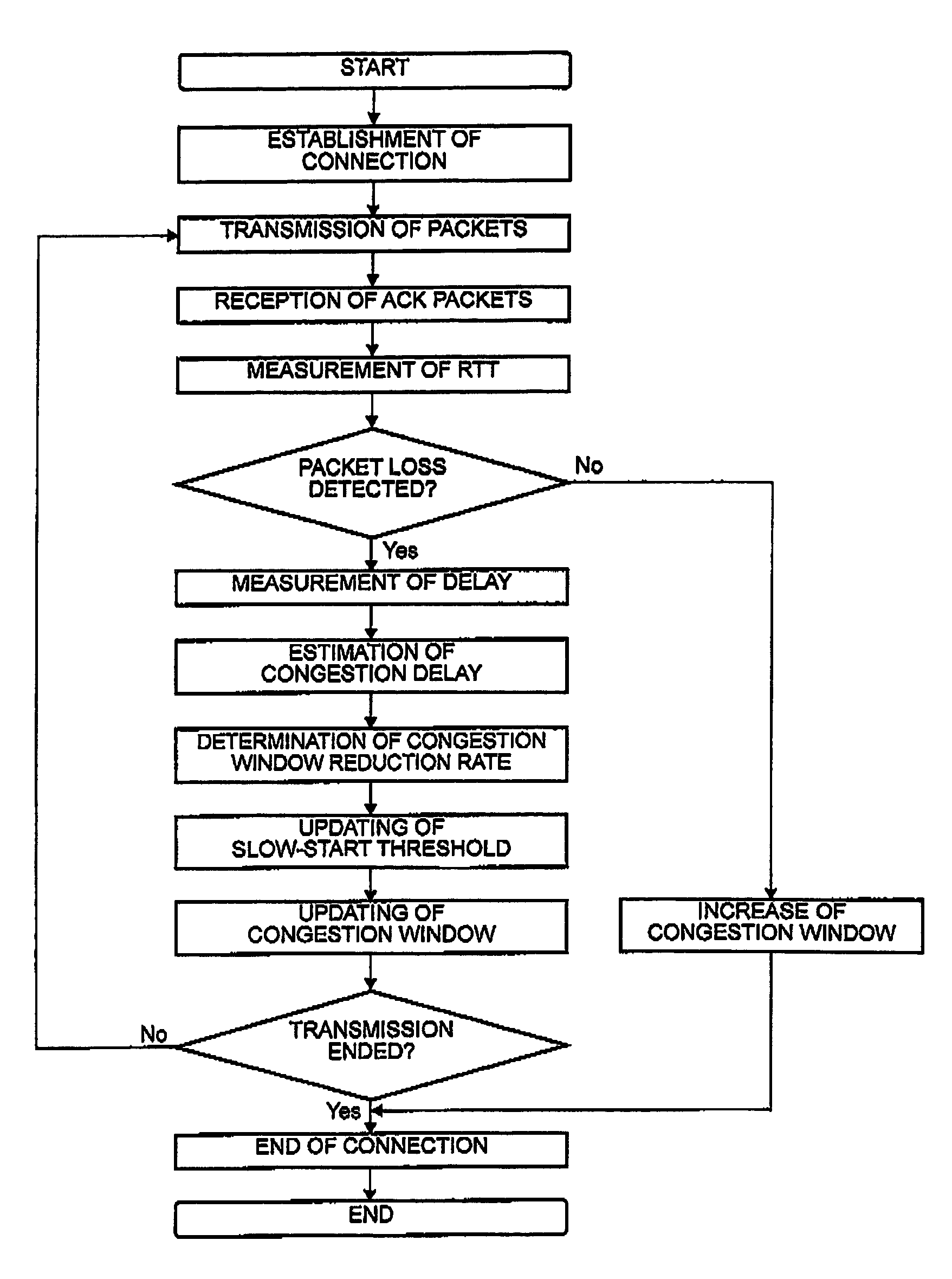
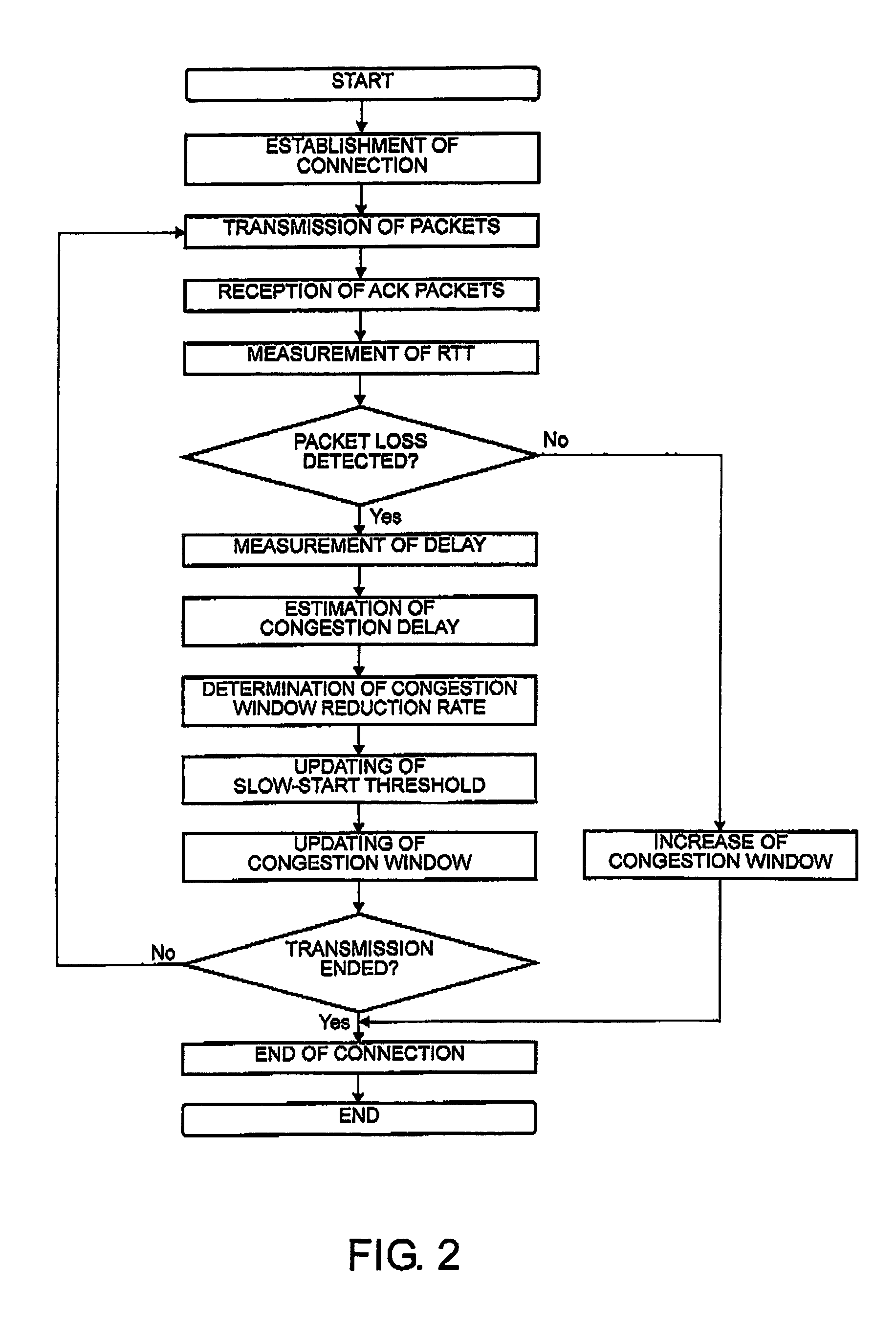
In a communication system for transmitting and receiving data between a plurality of terminals via a network through a session relay for relaying communication between the terminals, each of the terminals or the session relay measures a one-way or a round-trip delay time in the network, determines a threshold delay time at which network congestion is judged. With reference to a delay time upon detection of packet loss and the threshold delay time, estimation is made about the possibility that the packet loss results from congestion. A congestion window is changed with reference to the possibility upon detection of the packet loss.

Description

BACKGROUND OF THE INVENTION[0001]This invention relates to a communication system, a communication terminal, a session relay, and a communication protocol and, in particular, to a communication system, a communication terminal, a session relay, and a communication protocol, each of which is capable of maintaining high throughput even if a packet loss is frequently caused to occur.[0002]TCP (Transmission Control Protocol) is known as a protocol that is most frequently used in a fourth-layer protocol for data communication over the internet. By the use of the TCP, it is possible to realize reliable communication between a transmitting terminal and a receiving terminal without loss of data along a communication path. The TCP provides a congestion control function of appropriately controlling a congestion window depending upon a congestion condition of a network. If no congestion occurs in the network, the congestion window is given a large size to increase a transmission bandwidth. If ...

Claims


Application Information

Patent Timeline
Patent Type & Authority Patents(United States)
IPC IPC(8): H04L12/26
CPCH04L1/187H04L69/16H04L69/163H04L1/1809H04L2001/0092
Inventor SHIMONISHI, HIDEYUKISANADIDI, M. YAHYAGERLA, MARIO
Owner NEC CORP
Learn More