
Discharge from grinding mills

a technology of grinding mills and discharges, applied in the direction of solid separation, sorting, grading, etc., can solve problems such as discharge blockages, and achieve the effect of maximising the release of fine ground particles

Active Publication Date: 2010-07-20
F L SMIDTH & CO AS
View PDF6 Cites 2 Cited by
  • Summary
  • Abstract
  • Description
  • Claims
  • Application Information

AI Technical Summary

Benefits of technology

This configuration enhances the discharge of fine ground particles, reduces blockages, and allows for the return of coarse particles to the grinding chamber, improving the efficiency and reliability of the grinding process by optimizing particle size separation and preventing entrapment.

Problems solved by technology

The resultant higher velocity of mill contents can more readily lead to blockages at discharge.

Method used


Image

  • Discharge from grinding mills
  • Discharge from grinding mills
  • Discharge from grinding mills

Examples


Embodiment Construction

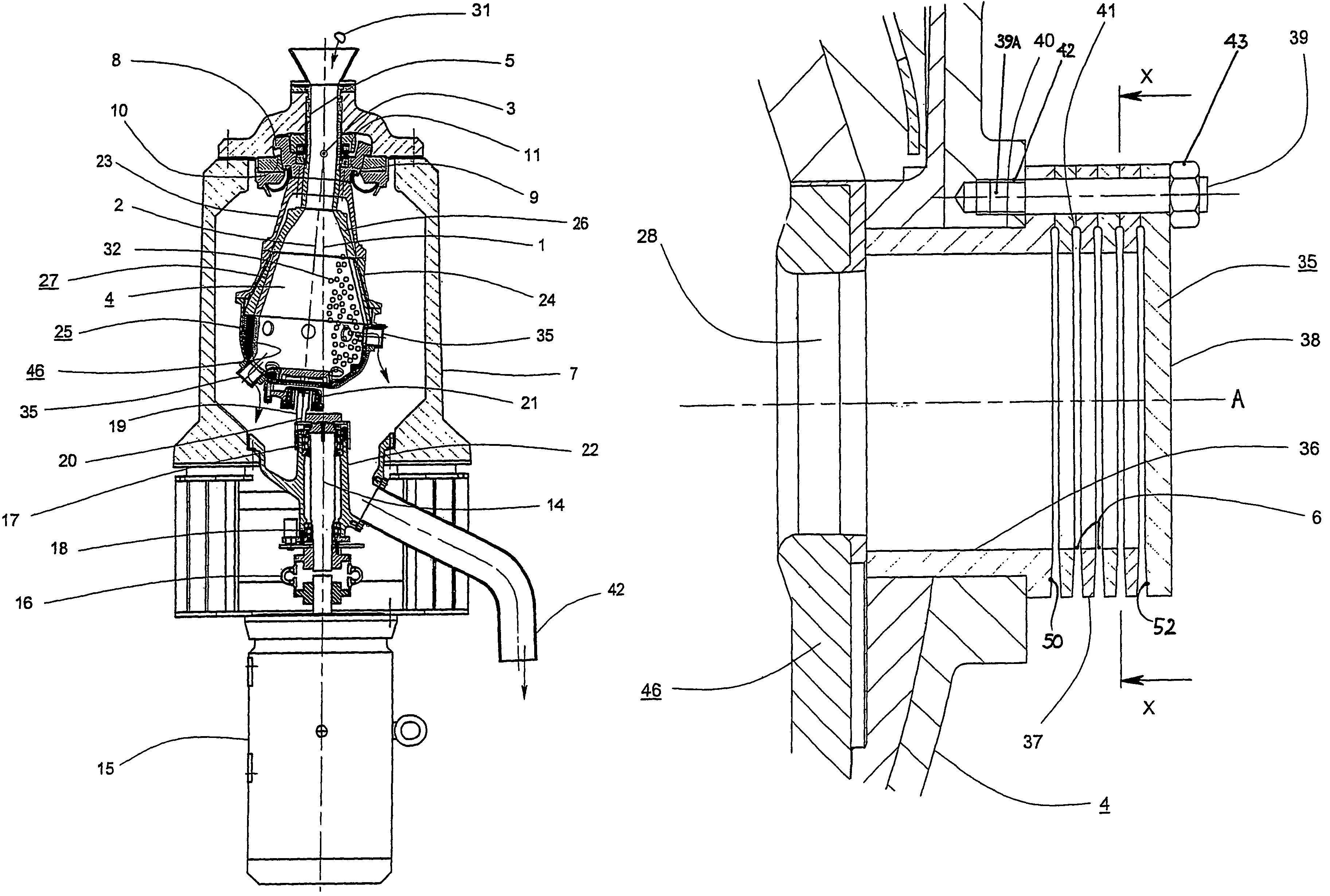
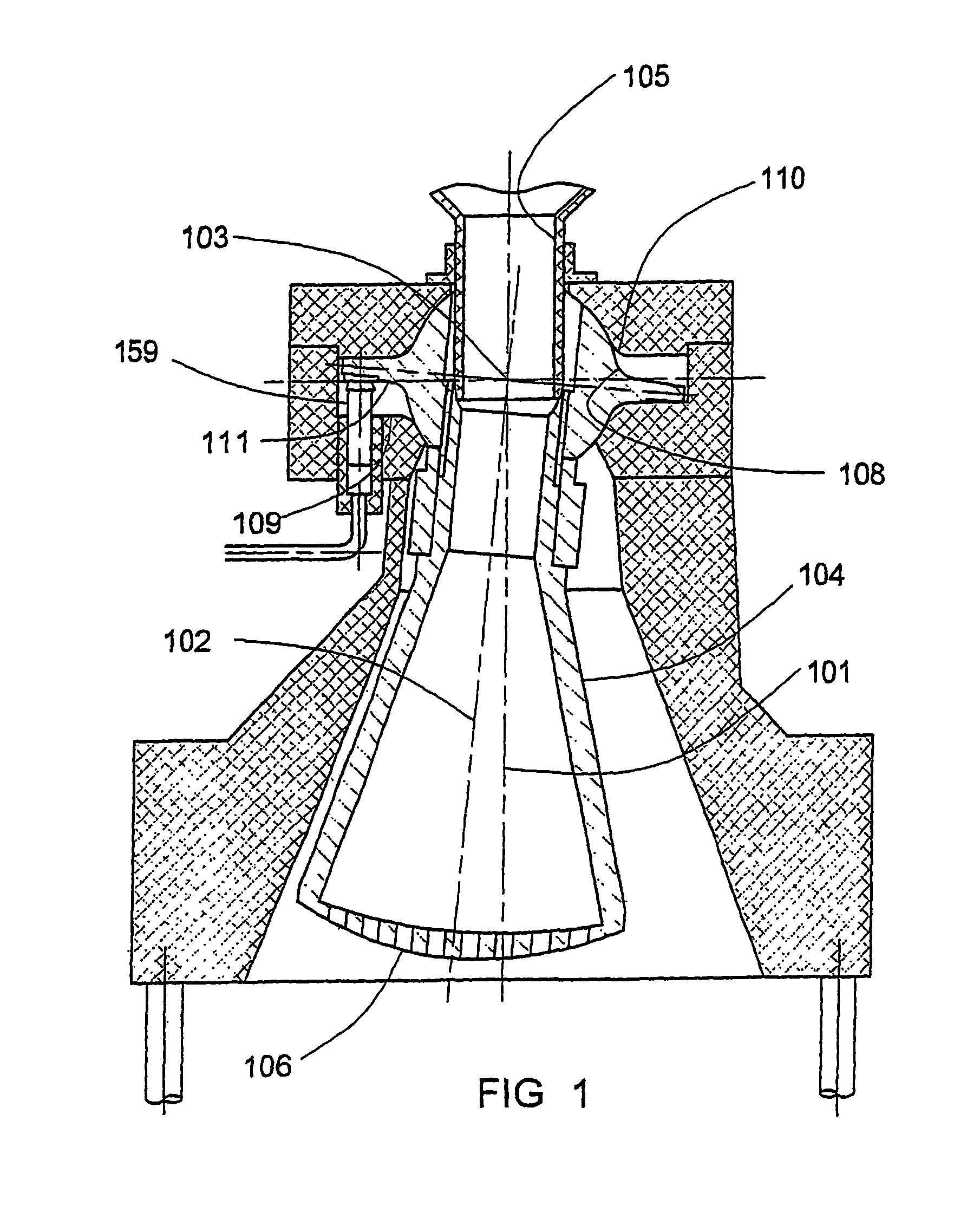
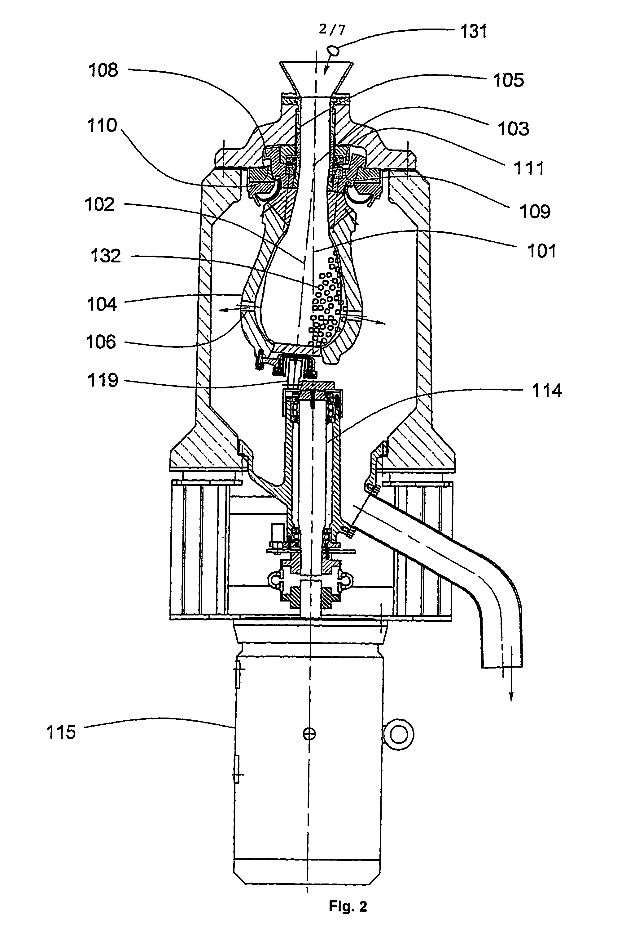
[0050]Referring firstly to FIGS. 1 and 2, cross sections through two known centrifugal grinding mills are shown. Screening element arrangements as described below can be employed with either of the grinding mills depicted in FIGS. 1 and 2, and may also be employed with other grinding mill arrangements.

[0051]Each of FIGS. 1 and 2 shows a grinding chamber 104, having an axis of symmetry 102, which rotates about a fixed axis 101, and intersects therewith at a point of nutation symmetry 103. The chamber is constrained to perform nutating motion by the engagement of complementary annular bearing surface pairs 109 and 111, and 108 and 110, which together form a bearing that is symmetrical about the point of nutation symmetry 103. This bearing limits the amplitude of nutating motion.

[0052]Feed material, typically in the form of a dry coarse granular material 131, or as a suspension of coarse particles in a fluid, or as a combination of both of these alternatives, is fed into the grinding c...


PUM


Abstract

A screening element can be mounted at a discharge passage of a grinding mill chamber. The discharge passage is positioned in use to receive ground particles moving thereinto in a discharge direction. The screening element comprises one or more openings defined therein which are oriented such that ground particles pass therethrough in a direction that is oblique with respect to the discharge direction. The grinding mill chamber may form part of a centrifugal grinding mill.

Description

TECHNICAL FIELD[0001]This disclosure relates to the discharge of ground particles from grinding mills such as centrifugal grinding mills.BACKGROUND TO THE DISCLOSURE[0002]Centrifugal grinding mills are employed for the comminution of solid particles, for example, mineral ores. Compared with tumbling mills (which are limited by gravitational acceleration), centrifugal grinding mills impart centrifugal acceleration to the mill contents as a consequence of a gyrating motion, greatly enhancing the rate of comminution. The resultant higher velocity of mill contents can more readily lead to blockages at discharge.SUMMARY OF THE DISCLOSURE[0003]In this disclosure there is firstly provided a screening element for mounting at a discharge passage of a grinding mill chamber. The discharge passage is positioned in use to receive ground particles moving thereinto in a discharge direction. The screening element comprises one or more openings defined therein which are oriented such that ground par...

Claims


Application Information

Patent Timeline
Patent Type & Authority Patents(United States)
IPC IPC(8): B02C23/16B02C17/14B02C17/18
CPCB02C17/14B02C17/181B02C17/1855B02C23/16B02C17/00
Inventor HUNTER, JAMES WILLIAM
Owner F L SMIDTH & CO AS
Learn More