Vehicle-to-vehicle communication apparatus, vehicle-to-vehicle communication system, and method of determining applicability of moving image information to an application program
a technology of vehicle-to-vehicle communication and application program, which is applied in the direction of two-way working system, navigation instrument, television system scanning details, etc., can solve the problems that the applicability of moving image information to application programs is not taken into account at all, and the information acquired from another vehicle via vehicle-to-vehicle communication is not always applicable to all application programs, etc., to achieve the effect of reducing the size of the data, reducing the cost of operation
- Summary
- Abstract
- Description
- Claims
- Application Information
AI Technical Summary
Benefits of technology
Problems solved by technology
Method used
Image
Examples
first embodiment
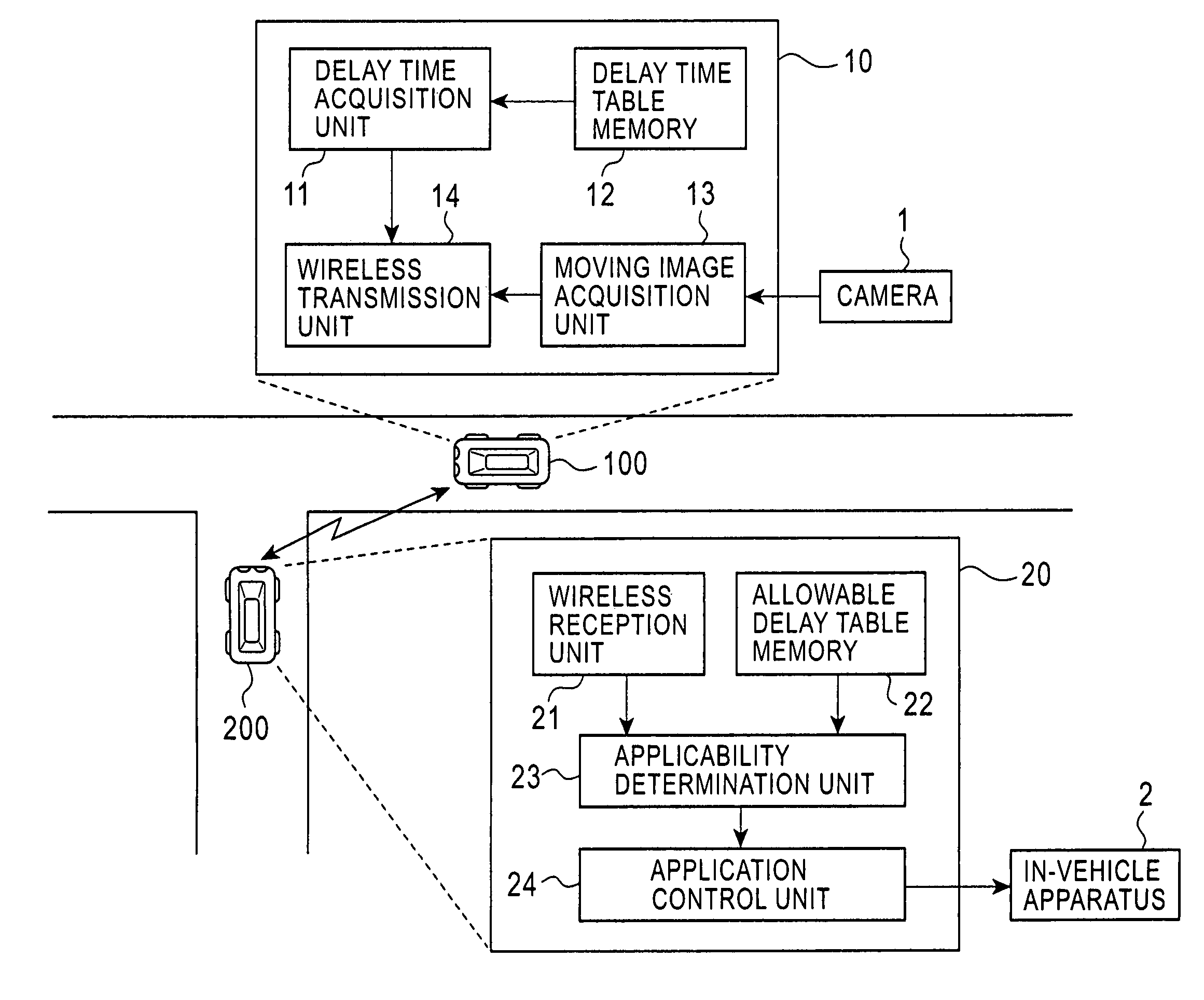
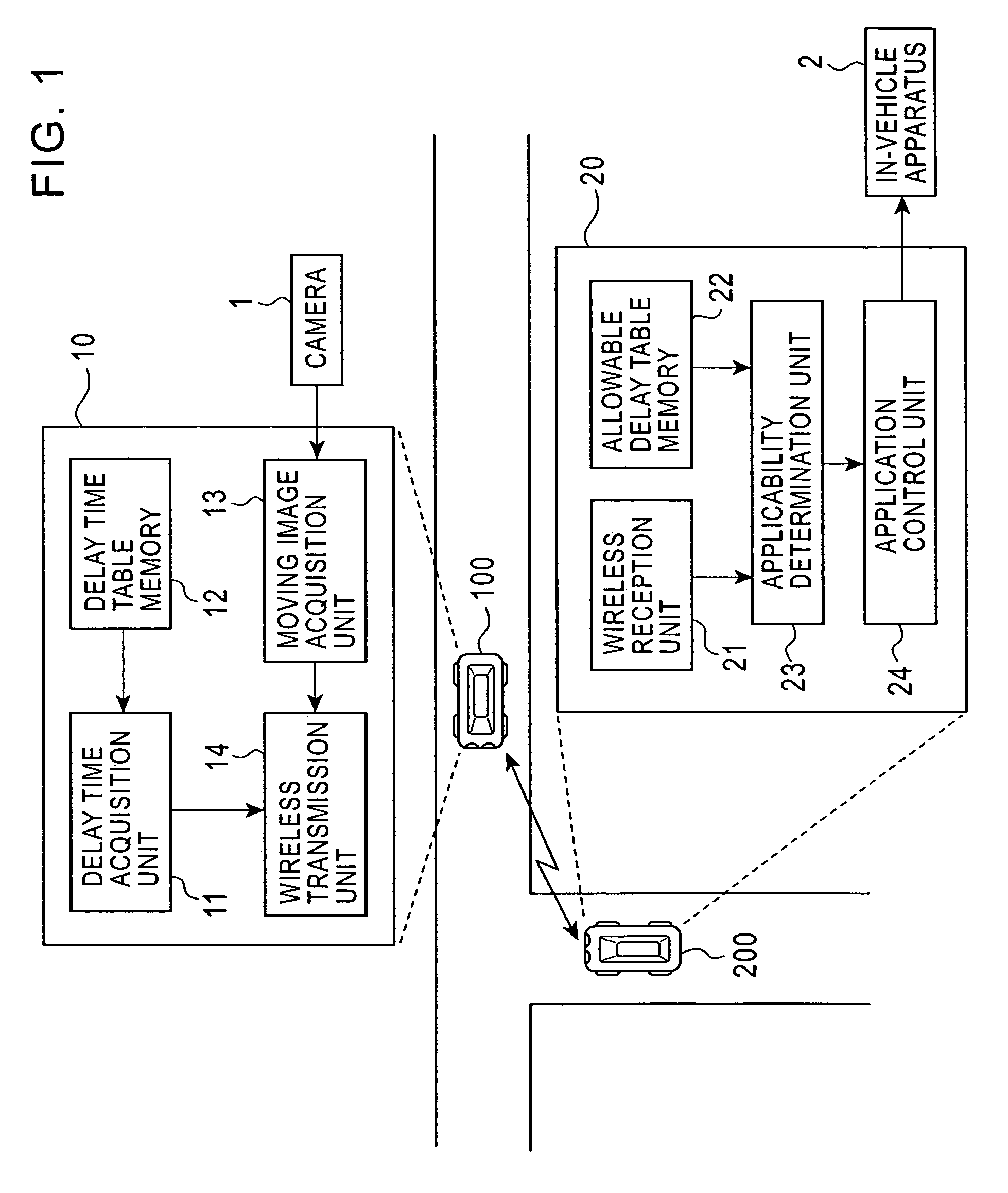
[0028]A first embodiment of the present invention is described below with reference to the accompanying drawings. FIG. 1 is a functional block diagram showing a vehicle-to-vehicle communication apparatus and a vehicle-to-vehicle communication system using the vehicle-to-vehicle communication apparatus according to the first embodiment. As shown in FIG. 1, the vehicle-to-vehicle communication system according to the first embodiment includes a first vehicle-to-vehicle communication apparatus 10 installed in a first vehicle 100, and a second vehicle-to-vehicle communication apparatus 20 installed in a second vehicle 200 whereby moving image information can be wirelessly transmitted between the vehicle-to-vehicle communication apparatus 10 and 20.
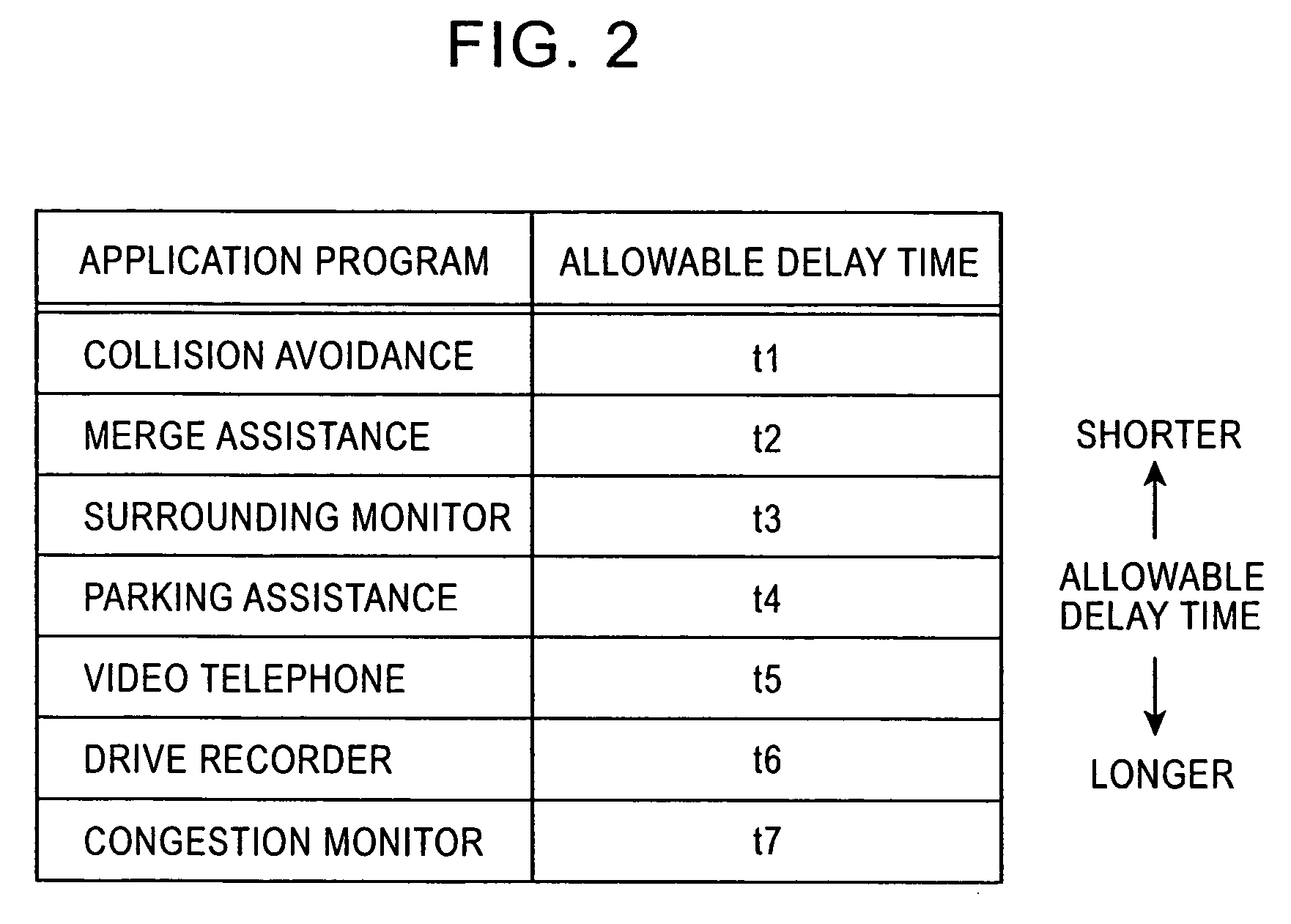
[0029]The first vehicle-to-vehicle communication apparatus 10 includes, as functional components, a delay time acquisition unit 11, a delay time table memory 12, a moving image acquisition unit 13, and a wireless transmission unit 14. The dela...
second embodiment
[0046]A second embodiment of the present invention is described below with reference to the accompanying drawings. FIG. 4 is a functional block diagram showing a vehicle-to-vehicle communication apparatus and a vehicle-to-vehicle communication system using the vehicle-to-vehicle communication apparatus according to the second embodiment. In FIG. 4, parts similar to those in FIG. 1 are denoted by similar reference numerals, and a duplicated explanation thereof is omitted.
[0047]As shown in FIG. 4, the vehicle-to-vehicle communication system according to the second embodiment includes a first vehicle-to-vehicle communication apparatus 30 installed in a first vehicle 100 and a second vehicle-to-vehicle communication apparatus 40 installed in a second vehicle 200 whereby moving image information can be wirelessly transmitted between the vehicle-to-vehicle communication apparatus 30 and 40.
[0048]The first vehicle-to-vehicle communication apparatus 30 includes, as functional components, a ...
third embodiment
[0059]A third embodiment of the present invention is described below with reference to the accompanying drawings. FIG. 6 is a functional block diagram showing a vehicle-to-vehicle communication apparatus and a vehicle-to-vehicle communication system using the vehicle-to-vehicle communication apparatus according to the third embodiment. In FIG. 6, parts similar to those in FIG. 4 are denoted by similar reference numerals, and a duplicated explanation thereof is omitted.
[0060]As shown in FIG. 6, the vehicle-to-vehicle communication system according to the third embodiment includes a first vehicle-to-vehicle communication apparatus 50 installed in a first vehicle 100 and a second vehicle-to-vehicle communication apparatus 60 installed in a second vehicle 200 whereby moving image information can be wirelessly transmitted between the vehicle-to-vehicle communication apparatus 50 and 60.
[0061]The first vehicle-to-vehicle communication apparatus 50 includes, as functional components, a del...
PUM
 Abstract
Description
Claims
Application Information
 - R&D
- Intellectual Property
- Life Sciences
- Materials
- Tech Scout
- Unparalleled Data Quality
- Higher Quality Content
- 60% Fewer Hallucinations
Browse by: Latest US Patents, China's latest patents, Technical Efficacy Thesaurus, Application Domain, Technology Topic, Popular Technical Reports.
© 2025 PatSnap. All rights reserved.Legal|Privacy policy|Modern Slavery Act Transparency Statement|Sitemap|About US| Contact US: help@patsnap.com


