Sample measuring device

a technology of measuring device and sample, which is applied in the direction of positive displacement liquid engine, laboratory glassware, instruments, etc., can solve the problems of high production cost and achieve the effects of low cost, high reliability of photometric analysis, and simple construction

Inactive Publication Date: 2010-07-06
ARKRAY INC
View PDF25 Cites 6 Cited by
  • Summary
  • Abstract
  • Description
  • Claims
  • Application Information

AI Technical Summary

Benefits of technology

[0009]In the above sample measuring device, communication is established between the reagent melting / mixing means and the measuring chamber and, when there are a plurality of reagent melting / mixing means, they are arranged in series, whereby communication is established between the reagent melting / mixing means and the measuring chamber on the downstream side thereof. Thus, it is possible to cause the sample to successively react with not only one but also more than one kind of reagents. Further, the sample and the reagents are reliably mixed and agitated together prior to photometric analysis, thereby achieving an improvement in the reliability of the photometric analysis.
[0011]The reagents used in the conventional devices are freeze-dried ones. A freeze-dried reagent requires the production steps of freezing, vacuum drying, etc., resulting in a rather high production cost. In contrast, the present invention allows use of a coating reagent, which can be obtained at low production cost.
[0018]In this way, it is possible to measure the sample blank in the measuring chamber, that is, the cuvette, for performing measurement on the sample that is to react with the reagent, and it is possible to perform sample blank correction without any inter-cuvette difference on a sample that will affect the measurement value, such as a chyle specimen or a hemolysis specimen, whereby it is possible to obtain a more accurate measurement value.
[0022]Further, it is possible to provide an air vent hole at least in the reagent melting / mixing means. Due to this air vent hole, it is possible to move the sample smoothly to the downstream side.
[0028]As described above, in accordance with the present invention, communication is established between the reagent melting / mixing means and the measuring chamber (in the case in which there are provided a plurality of reagent melting / mixing means, these are caused to communicate with each other in series, with the reagent melting / mixing means on the downstream side communicating with the measuring chamber), so that it is possible to cause a sample to react with one or more kinds of reagent.
[0029]Further, the sample and the reagent are reliably mixed and agitated together prior to photometric analysis to thereby achieve high reliability in photometric analysis, and it is possible to provide a superior sample measuring device which is of simple construction and which can be produced at low cost and handled easily.

Problems solved by technology

A freeze-dried reagent requires the production steps of freezing, vacuum drying, etc., resulting in a rather high production cost.

Method used


Image

  • Sample measuring device
  • Sample measuring device
  • Sample measuring device

Examples


embodiment 1

[0046]In the following, a sample measuring device according to Embodiment 1 of the present invention will be described in detail with reference to the relevant drawings.

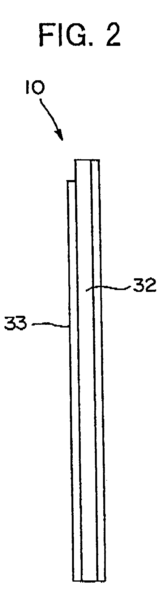
[0047]FIGS. 1 and 2 show a sample measuring device 10 according to an embodiment of the present invention. As is apparent from FIGS. 1 and 2, which are a plan view and a side view, respectively, the sample measuring device 10 of this embodiment is generally formed as a thin and narrow plate, one surface of which is equipped with first and second reagent melting / mixing means 11-1 and 11-2.

[0048]Here, the upper and lower sides of the sample measuring device 10 as seen in the drawing will be referred to as the upstream and downstream sides, respectively, with respect to the sample flowing direction.

[0049]While it is possible, in the sample measuring device of the present invention, to provide only one reagent melting / mixing means, this embodiment is equipped, as stated above, with two reagent melting / mixing means (the f...

embodiment 2

[0066]In the example shown in FIG. 3, there is provided, on the centrifugal side of the measuring chambers 13 and 14, a disposal chamber 28 a part from the over flow chamber 27. The disposal chamber 28 serves to dispose of and recover the sample which has flowed into the measuring chambers 13 and 14 and undergone measurement; the disposal chamber 28 communicates with the measurement chambers 13 and 14 through a tubule 30.

[0067]Further, as shown in FIG. 3, in this example, there is formed a communication passage 31 further extending from the first back-flow preventing chamber 16 in the centrifugal direction and communicating with the fourth back-flow preventing chamber 24. As stated above, the fourth back-flow preventing chamber 24 communicates with the measuring chambers 13 and 14 through the passage 25 and the fifth back-flow preventing chamber 26, with the result that, due to the presence of this communication passage 31, the sample supply chamber 12 communicates with the measurin...

embodiment 3

[0099]FIG. 8 shows a main portion of a sample measuring device according to another embodiment of the present invention. In FIG. 8, the components that are the same as or equivalent to those of the sample measuring device 10 shown in FIG. 3 are indicated by the same reference numerals, and a detailed description of such components will be omitted.

[0100]The construction of the sample measuring device 100 of the embodiment shown in FIG. 8 differs from that of the sample measuring device 10 shown in FIG. 3 in that, in the flow passage from the measuring chambers 13 and 14 to the overflow chamber 27, there is used a tubule 102 whose total length is increased through a lateral U-shaped configuration as a communication means between the measuring chambers 13 and 14 and the back-flow preventing chamber 29.

[0101]In general, when the length of the tubule 102 is small, back flow or drying of the liquid may occur when measurement is performed with the rotor being at rest or reduced in rotating...


PUM

PropertyMeasurementUnit
depthaaaaaaaaaa
cell lengthaaaaaaaaaa
depthaaaaaaaaaa

Abstract

The present invention provides a sample measuring device capable of allowing not only one but more than one kind of samples to react with a reagent, and enhancing a reliability in photometric analysis accuracy by reliably mixing and agitating the sample and the reagent prior to the photometric analysis. The device includes a reagent melting / mixing means, a sample supply chamber positioned on the upstream side of, and communicating with, the reagent melting / mixing means when the sample is allowed to flow into the reagent melting / mixing means, and at least one measuring chamber positioned on the downstream side of, and communicating with, the reagent melting / mixing means, wherein the sample supply chamber, the reagent melting / mixing means, and the measuring chamber are arranged sequentially from the upstream to the downstream directions of the flow passage, with the sample supply chamber positioned on the upstream side with respect to the sample flow by a sample moving means. When a centrifugal machine is used as a reagent moving means and the sample measuring device is installed and used with its imaginary axis kept along the radial direction of a rotor of the centrifugal machine, the sample supply chamber can be provided to be positioned on the radially inner side of the rotor in the centrifugal machine.

Description

TECHNICAL FIELD[0001]The present invention relates to a sample measuring device, and more specifically to a sample measuring device which can be suitably used when, for example, optically measuring the properties of a reaction product obtained by mixing a reagent with blood plasma, biological liquid, or the like for reaction.BACKGROUND ART[0002]An apparatus for analyzing blood plasma, biological liquid or the like is already well-known, as disclosed in JP 10-501340 A (PCT), etc. In the “Modified Siphons for Improved Metering Precision” disclosed in the above-mentioned publication, the rotor of a centrifugal separator is equipped with a blood application chamber, a blood plasma measuring chamber, a retention chamber, a diluting agent measuring chamber, a mixing chamber, a measurement cuvette, etc.; in particular, the blood plasma measuring chamber and the mixing chamber communicate with each other through a siphon, wherein the positional relationship between the siphon inlet communic...

Claims


Application Information

Patent Timeline
Patent Type & Authority Patents(United States)
IPC IPC(8): G01N33/00B01F13/00B01L3/00G01N33/49G01N35/00G01N35/08
CPCB01F13/0064B01F13/0094B01L3/5027B01L3/50273B01L3/502738G01N33/491G01N35/08B01L2200/0621B01L2300/0864B01L2300/0867B01L2300/087B01L2400/0409B01L2400/0481B01L2400/0633B01L2400/0655G01N2035/00495G01N2035/00544B01F33/3017B01F33/304
Inventor KOIKE, MASUFUMIMIZUTANI, SATORU
Owner ARKRAY INC
Why Eureka
Try Eureka