
Orthogonal signal generation using vector spreading and combining

a vector spreading and combining technology, applied in the field of orthogonal signal generation, can solve the problems of certain inaccuracy of techniques and implementation trade-offs, and achieve the effect of reducing the number of critical manipulations

Inactive Publication Date: 2010-06-29
PARKER VISION INC
View PDF5 Cites 178 Cited by
  • Summary
  • Abstract
  • Description
  • Claims
  • Application Information

AI Technical Summary

Benefits of technology

This approach reduces hardware complexity and power consumption while maintaining accuracy in orthogonal signal generation, offering a more efficient alternative to traditional methods.

Problems solved by technology

These techniques possess certain inaccuracies and implementation tradeoffs.

Method used


Image

  • Orthogonal signal generation using vector spreading and combining
  • Orthogonal signal generation using vector spreading and combining
  • Orthogonal signal generation using vector spreading and combining

Examples


case 2

5.2. Case 2

[0151]Using the previous notation two vectors are formed as follows;

V0={tilde over (V)}1−({tilde over (V)}3+{tilde over (Δ)}14)

V+90={tilde over (V)}2−({tilde over (V)}4+{tilde over (Δ)}24)

[0152]The basis vectors are redrawn in FIGS. 13 and 14 for reference.

{tilde over (V)}45={tilde over (V)}1−({tilde over (V)}3+{tilde over (Δ)}13)=(α1−α3)+(β1−β3)j−{tilde over (Δ)}13

{tilde over (V)}135=({tilde over (V)}2+2{tilde over (Δ)}12)−({tilde over (V)}4+{tilde over (Δ)}24)=(α2−α4)+(β2−β4)j−{tilde over (Δ)}24+2{tilde over (Δ)}12

α13=α1−α3

β13=β1−β3

α24=α2−α4

β24=β2−β4

[0153]All of the correction (error) vectors are included such that V45 and V135 are orthogonal. Notice the vectors on the real axis and imaginary axis. V135 and V45 are composed from those vectors, {right arrow over (x)}, −{right arrow over (x)}, {right arrow over (y)}. This is exactly the same form as that given in Section 5.1 for Case 1, i.e.,

{right arrow over (V)}135=−{right arrow over (x)}+{right arrow over (y)}

V45={righ...


PUM


Abstract

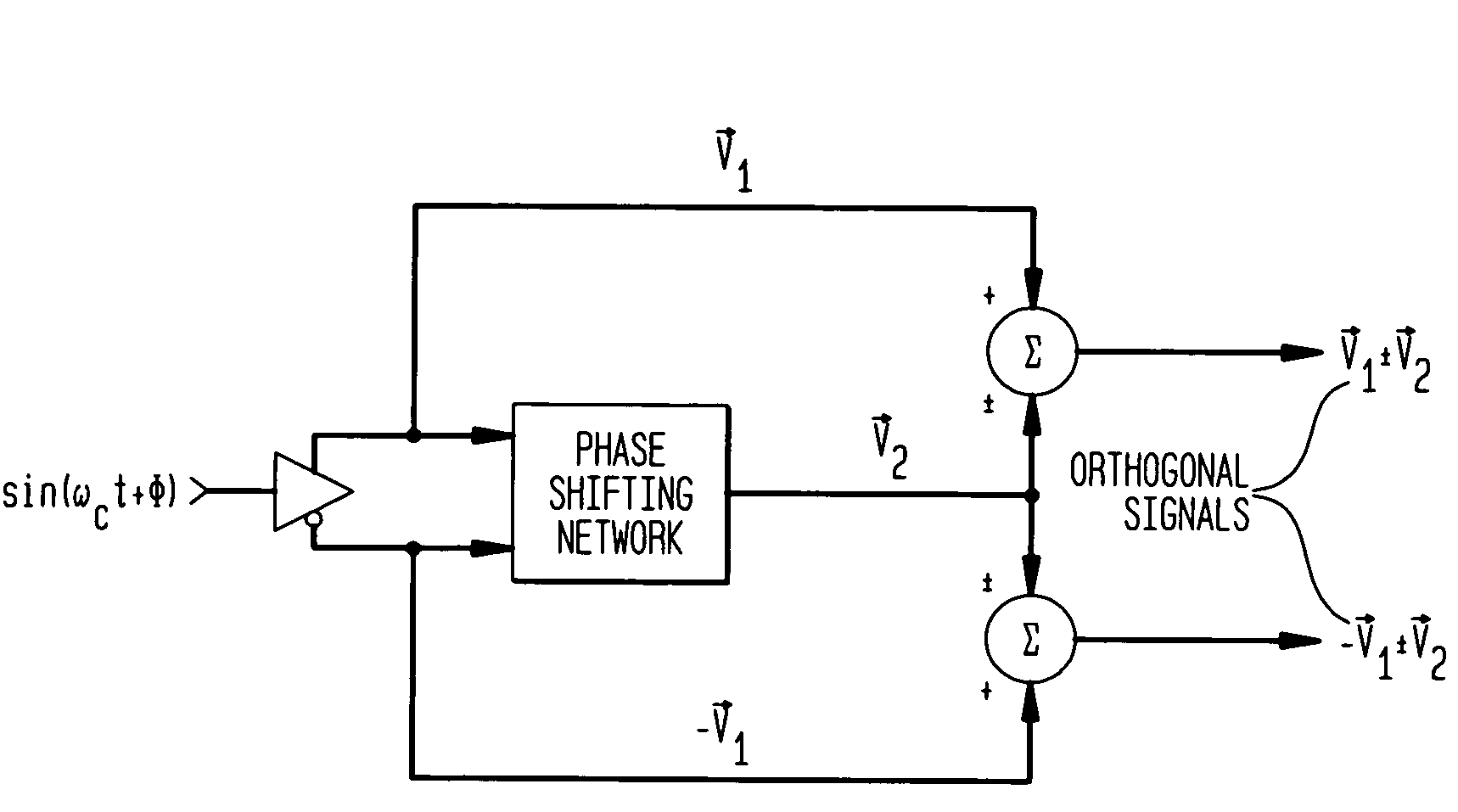
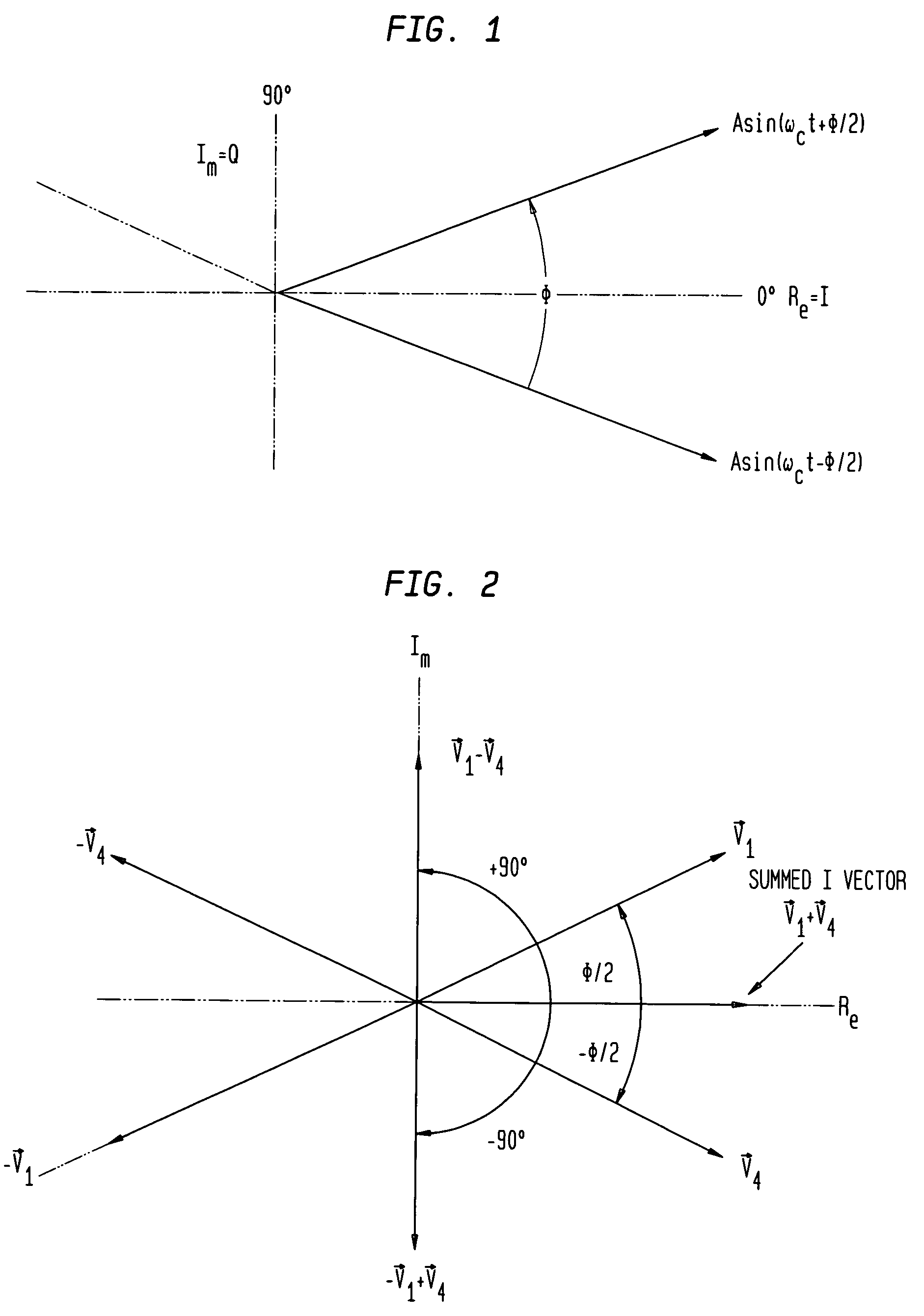
The present invention provides an approach for quadrature signal generation, which does not require orthogonal reference signals or nearly orthogonal reference signals as an input or given condition. The techniques provided herein can utilize a reference phase shift less than 90° but greater than 0°, along with an inversion to create orthogonal signals. The techniques provided here reduce the number of critical manipulations required from a hardware perspective.

Description

CROSS REFERENCE TO RELATED APPLICATION[0001]This application claims the benefit of U.S. Provisional Patent Application No. 60 / 620,925, titled “Methods and Systems for Orthogonal Signal Generation Using Vector Spreading and Combining,” which was filed on Oct. 22, 2004, and is incorporated herein by reference in its entirety.FIELD OF THE INVENTION[0002]The present invention is related to generation of orthogonal signals.BACKGROUND OF THE INVENTION[0003]Often in signal processing applications, particularly modulation and demodulation, orthogonal signals are required to transport and recover latent information relating to some complex passband waveform. Typically, analog techniques are used in RF modulators and demodulators to synthesize a 90° phase shift in a carrier or signal waveform to enable this processing. Passive and active components are used to generate delays at passband corresponding to phase shift at a frequency of interest. These techniques possess certain inaccuracies and...

Claims


Application Information

Patent Timeline
Patent Type & Authority Patents(United States)
IPC IPC(8): H04J11/00
CPCH03B27/00H04L27/0014H04L2027/0016
Inventor RAWLINS, GREGORY S.SORRELLS, DAVIDMILNE, GREGRAWLINS, MIKE
Owner PARKER VISION INC
Learn More