
Optical glass, preform for precision press molding and method of manufacturing thereof, optical element and method of manufacturing thereof

a technology of optical elements and optical glass, applied in the field of optical glass, can solve the problems of compromising productivity, causing crizzles and cracks, and sometimes affecting the cooling effect of the pressing mold,

Inactive Publication Date: 2010-06-29
HOYA CORP
View PDF10 Cites 2 Cited by
  • Summary
  • Abstract
  • Description
  • Claims
  • Application Information

AI Technical Summary

Benefits of technology

The present invention is about a special glass that can be used for precision press molding. The glass has a high refractive index and a specific Abbé number. It has a unique ratio that indicates its elongation relative to temperature. The glass has a maximum value of elongation at a specific temperature. The invention also includes a preform made of the glass, a method for manufacturing the preform, and a method for manufacturing optical elements using the glass. The technical effects of the invention include improved precision and accuracy in the manufacturing process for optical elements.

Problems solved by technology

In the course of manufacturing optical elements such as lenses by precision press molding, when the glass is precision press molded, damage sometimes occurs during cooling in the pressing mold.
Such damage consists of crizzles and cracking.
This is particularly prominent in the high refractive index and low dispersion glasses referred to above, and compromises productivity.
This phenomenon occurred when the glass was enclosed within the pressing mold, producing great stress in glass that had lost the ability to undergo plastic deformation.
However, the relatively weak structure of high refractive index and low dispersion glass falling within the above-stated optical constant ranges is thought to result in crizzles and cracking.

Method used


Image

  • Optical glass, preform for precision press molding and method of manufacturing thereof, optical element and method of manufacturing thereof
  • Optical glass, preform for precision press molding and method of manufacturing thereof, optical element and method of manufacturing thereof
  • Optical glass, preform for precision press molding and method of manufacturing thereof, optical element and method of manufacturing thereof

Examples


examples

[0100]The present invention will be further described below through examples. However, the present invention is not limited to the forms shown in the examples.

Manufacturing Optical Glass

[0101]Table 1 gives the glass compositions of Examples 1 to 18 and Comparative Examples 1 and 2. Various corresponding oxides, hydroxides, carbonates, and nitrates were employed as the starting materials of the various components for each of these glasses. The starting materials were weighed out so as to yield the compositions indicated in Table 1 following vitrification, thoroughly mixed, charged to a platinum crucible, melted at a temperature range of 1,200 to 1,300° C. in an electric furnace, homogenized by stirring, clarified, and cast in a metal mold that had been preheated to suitable temperature. The cast glass was cooled to the glass transition temperature and then directly introduced into an annealing furnace, where it was gradually cooled to room temperature. Various optical glasses were th...


PUM

PropertyMeasurementUnit
mole ratioaaaaaaaaaa
Tgaaaaaaaaaa
Abbé numberaaaaaaaaaa

Abstract

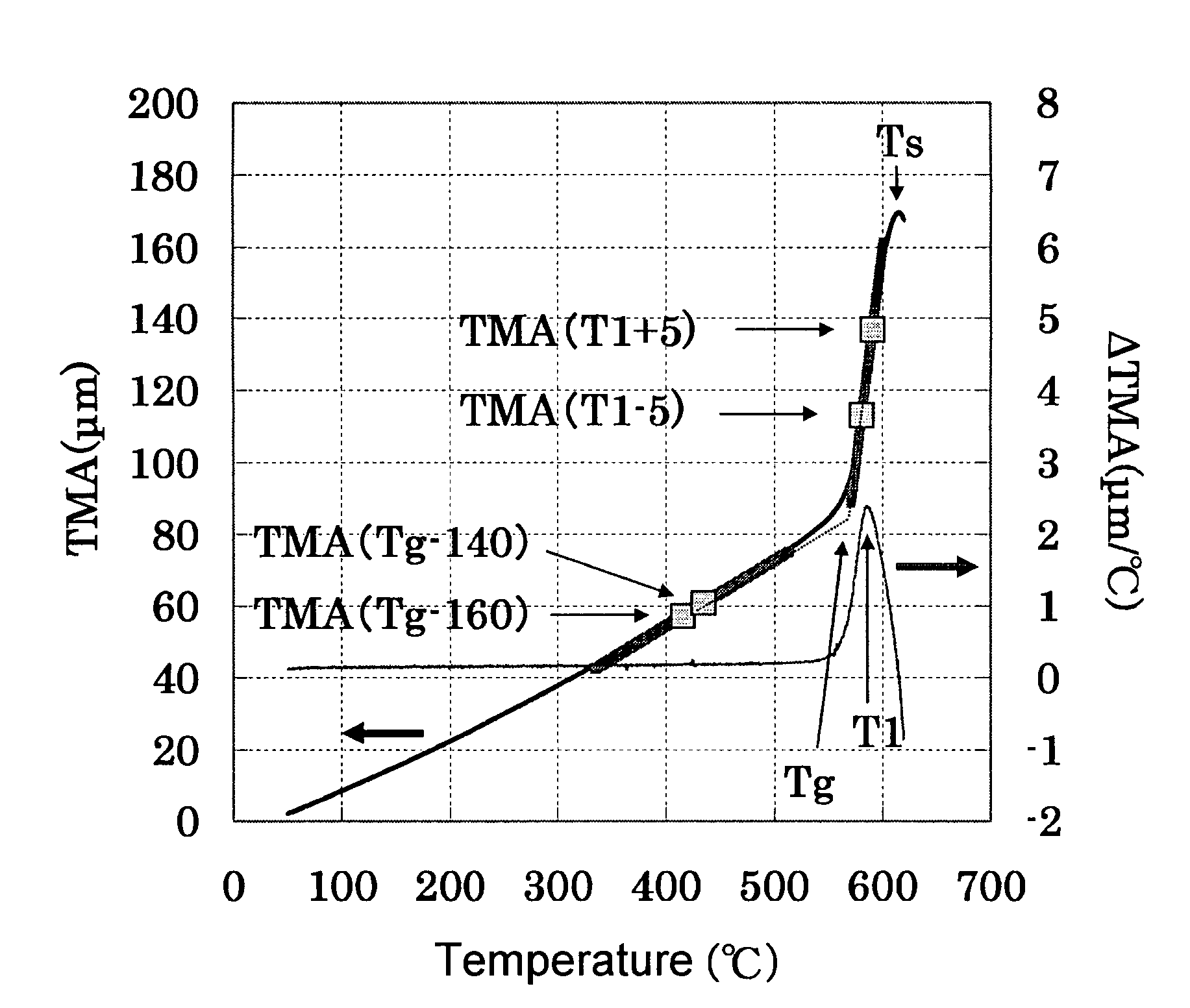
The present invention relates to an optical glass having a refractive index (nd) of greater than or equal to 1.65 and an Abbé number (ν (nu)d) of greater than or equal to 50 for use in precision press molding. The glass exhibits that a ratio α (alpha)1 / α (alpha)2 is less than 17 when temperature denoting maximum value of differential in amount of elongation of glass relative to temperature differential DELTAT (where DELTAT denotes a constant value of 1° C. or less) over a temperature range from glass transition temperature (Tg) to sag temperature (Ts) is denoted as T1, average coefficient of linear expansion over a range from T1−5° C. to T1+5° C. is denoted as alpha1, and average coefficient of linear expansion over a range from the glass transition temperature (Tg)−160° C. to the glass transition temperature (Tg)−140° C. is denoted as alpha2.

Description

CROSS-REFERENCE TO RELATED APPLICATIONS[0001]This application claims benefit of priority under 35 USC 119 to Japanese Patent Application No. 2006-82667 filed on Mar. 24, 2006, which is expressly incorporated herein by reference in its entirety.BACKGROUND OF THE INVENTION[0002]1. Field of the Invention[0003]The present invention relates to an optical glass having optical constants in the form of a refractive index (nd) of greater than or equal to 1.65 and an Abbé number (ν (nu)d) of greater than or equal to 50; a preform for precision press molding comprised of said glass; a method for manufacturing said preform; and a method for manufacturing optical elements comprised of said glass.[0004]2. Discussion of the Background[0005]The arrival of digital cameras and portable cellular phones equipped with cameras has resulted in the rapid progression of high integration and high functionality in devices employing optical systems. At the same time, the demand for high precision, light weight...

Claims


Application Information

Patent Timeline
Patent Type & Authority Patents(United States)
IPC IPC(8): C03C3/064C03C3/062C03B7/00C03B9/16C03B9/20
CPCC03C3/068C03B11/00C03B11/06C03B11/08
Inventor KASUGA, YOSHIKOFUJIWARA, YASUHIROZOU, XUELU
Owner HOYA CORP
Learn More