
Lightweight hub for rotors

a technology of rotors and hubs, applied in the direction of machines/engines, final product manufacture, electric generator control, etc., can solve the problems of structural inefficiency, waste of material production, and large cutouts in monolithic shell structures,

Active Publication Date: 2010-06-22
GENERAL ELECTRIC CO
View PDF30 Cites 5 Cited by
  • Summary
  • Abstract
  • Description
  • Claims
  • Application Information

AI Technical Summary

Benefits of technology

The solution results in a lighter, more structurally efficient hub that reduces weight and manufacturing costs while maintaining reliability, by distributing loads effectively and minimizing material requirements.

Problems solved by technology

Monolithic shell structures with large cutouts are structurally inefficient and wasteful of material to produce.
Moreover, large cutouts in monolithic shells result in stress concentrations, which further exacerbate structural inefficiency.
Structural inefficiency equates to excessive weight, and for structures such as wind turbines that are mounted on supporting towers, these supporting towers must be designed with capacity to support the excess weight.

Method used


Image

  • Lightweight hub for rotors
  • Lightweight hub for rotors
  • Lightweight hub for rotors

Examples


Embodiment Construction

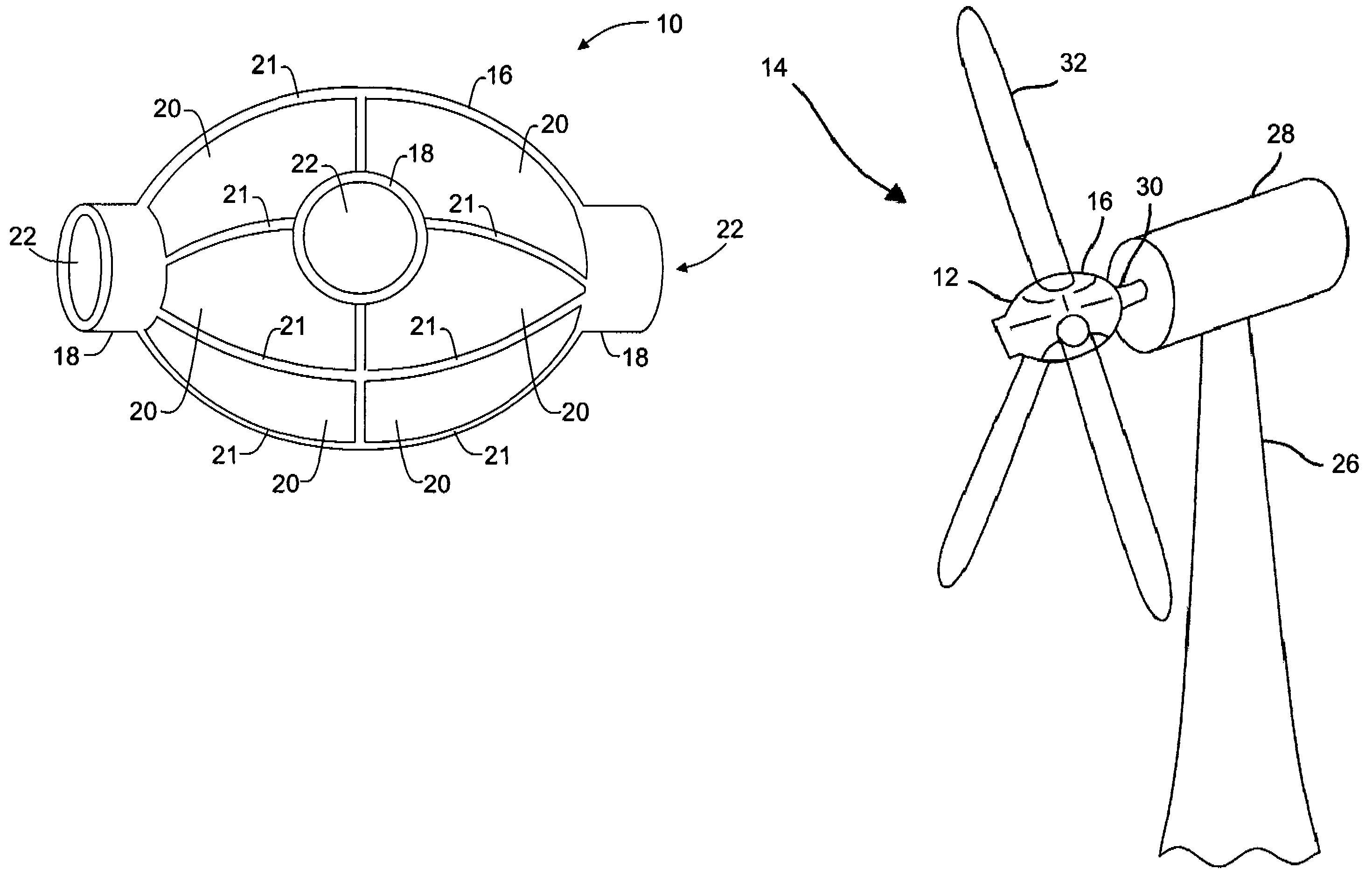
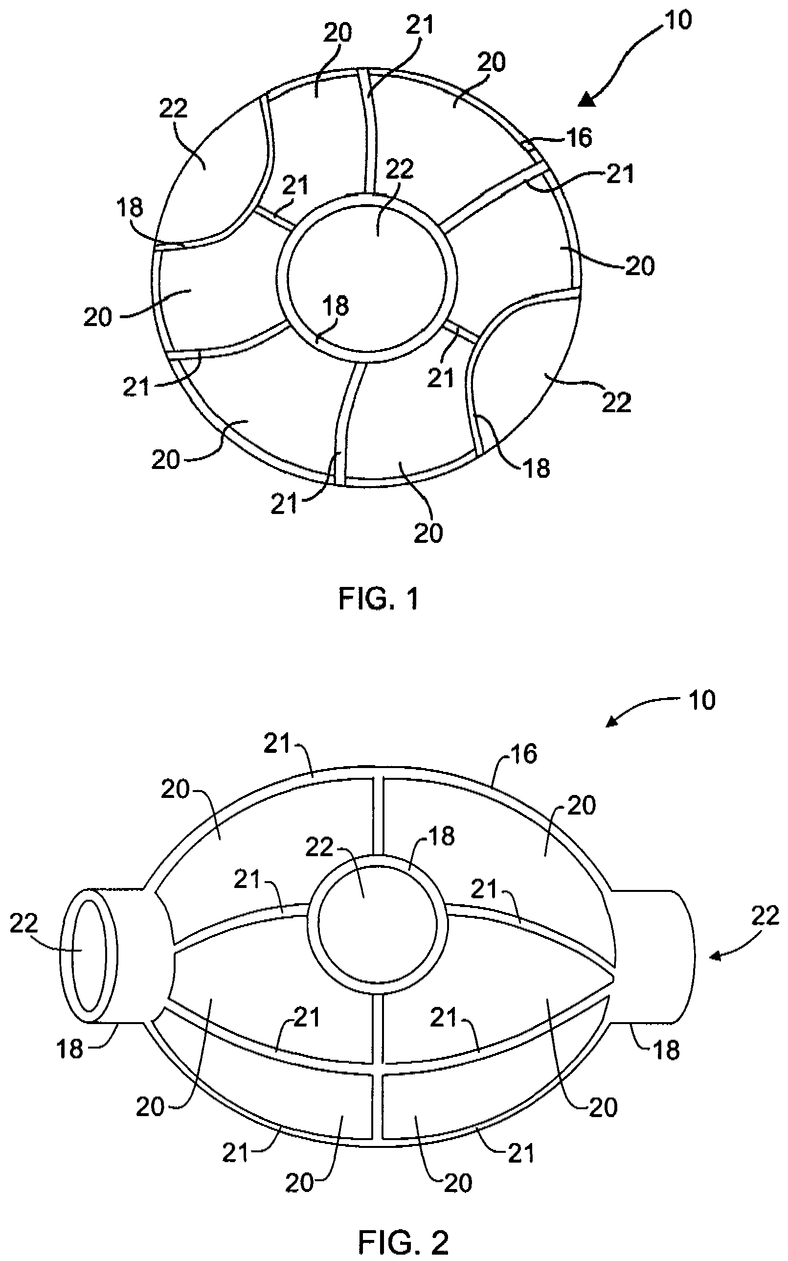
[0012]Some configurations of the present invention provide a stiffened shell structure for improved efficiency (i.e., increased load carrying capacity per unit weight). Also, some configurations of the present invention provide a space frame configured to carry primary torsion, bending and direct loading in a truss-like manner. Also provided in some configurations is a light-weight shell configured to act as shear wall to stabilize the frame and to carry shear loading. Formed truss members in some configurations “frame” cut-outs and provide stiffer cutouts. In addition, the frame eliminates stress concentrations because the primary loading is carried by the formed frame as direct tension / compression loads rather than as membrane loading in known monolithic shells.

[0013]Forming a space frame configuration of the present invention requires less material than forming a monolithic shell. Thin shell skins in some configurations can comprise metal or a composite material. Metal shell skin...


PUM


Abstract

A structure for a hub of a rotor includes a space frame having truss members configured to carry primary torsion, bending, and direct loading. The structure also includes a shell on the space frame configured to stabilize the space frame and carry shear loading.

Description

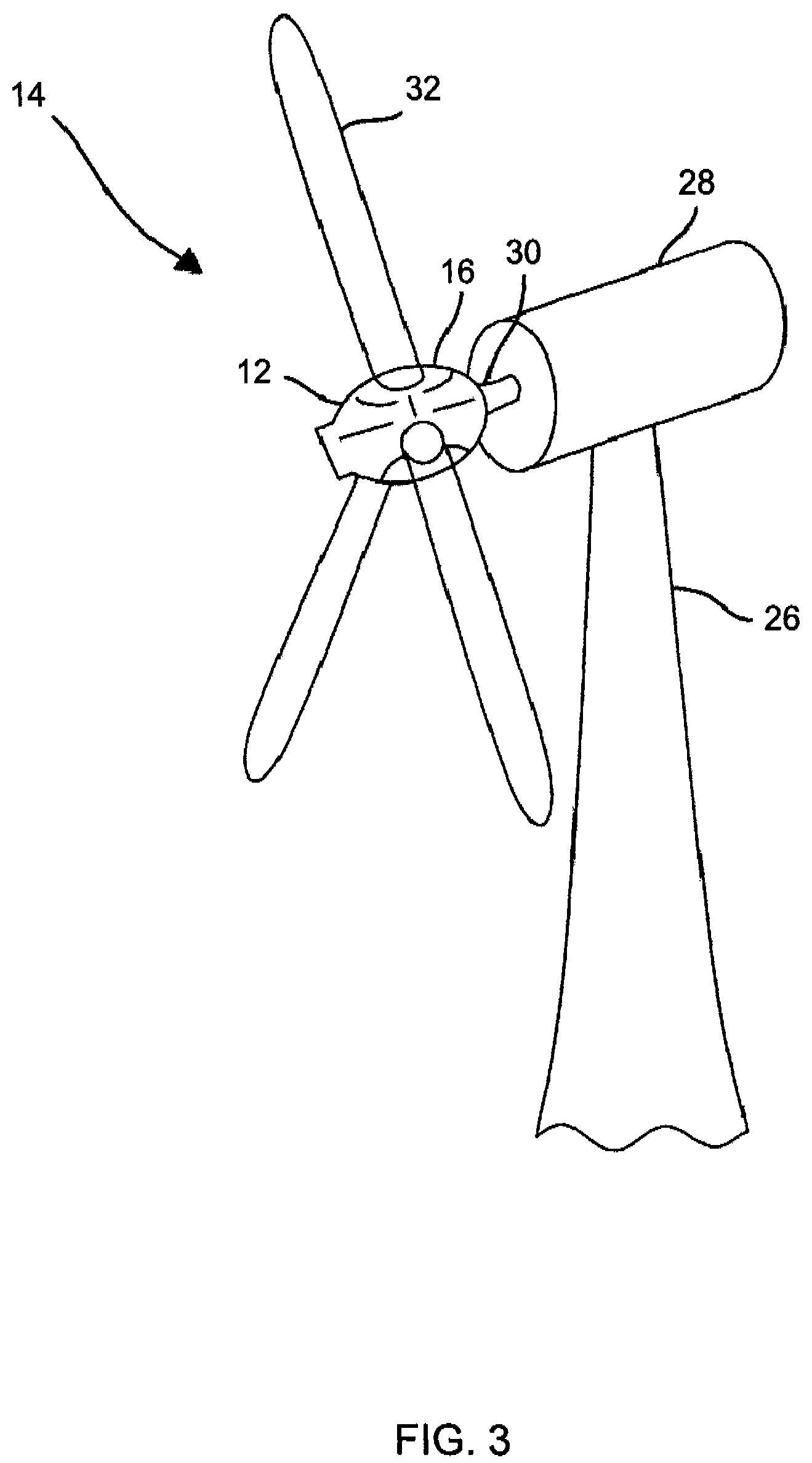
BACKGROUND OF THE INVENTION[0001]This invention relates generally to a lightweight hub structure, and more particularly to a hub structure including a space frame with truss members that is particularly suitable for use in wind turbine generators.[0002]Monolithic shell structures with large cutouts are structurally inefficient and wasteful of material to produce. Moreover, large cutouts in monolithic shells result in stress concentrations, which further exacerbate structural inefficiency.[0003]At least one known hub for a wind turbine includes a casting having a weight of approximately 68,000 pounds. This hub requires extensive machining to match multiple component interfaces. One known hub configuration typically has five large cutouts, including three for blade attachments, one for an output shaft, and one for a spinner. The combined weight of the hub plus the interfaced components, including pitch-drive mechanisms, can approach 100,000 pounds. Structural inefficiency equates to e...

Claims


Application Information

Patent Timeline
Patent Type & Authority Patents(United States)
IPC IPC(8): F03B3/12
CPCF03D1/0658F03D1/0691F05B2230/232F05B2240/14Y02E10/726F05B2280/6003F05C2253/04Y02E10/721F05B2260/301Y02E10/72Y02P70/50
Inventor CAIRO, RONALD RALPH
Owner GENERAL ELECTRIC CO
Learn More