
Gas generator launcher for small unmanned aerial vehicles (UAVs)

a gas generator and launcher technology, applied in the field of weapons deployment systems, can solve the problems of large size, cumbersome use, and high cost of typical launchers used for uavs

Inactive Publication Date: 2010-06-22
ARMY UNITED STATES OF AMERICA AS REPRESENTED BY THE SECREATRY OF THE
View PDF9 Cites 10 Cited by
  • Summary
  • Abstract
  • Description
  • Claims
  • Application Information

AI Technical Summary

Benefits of technology

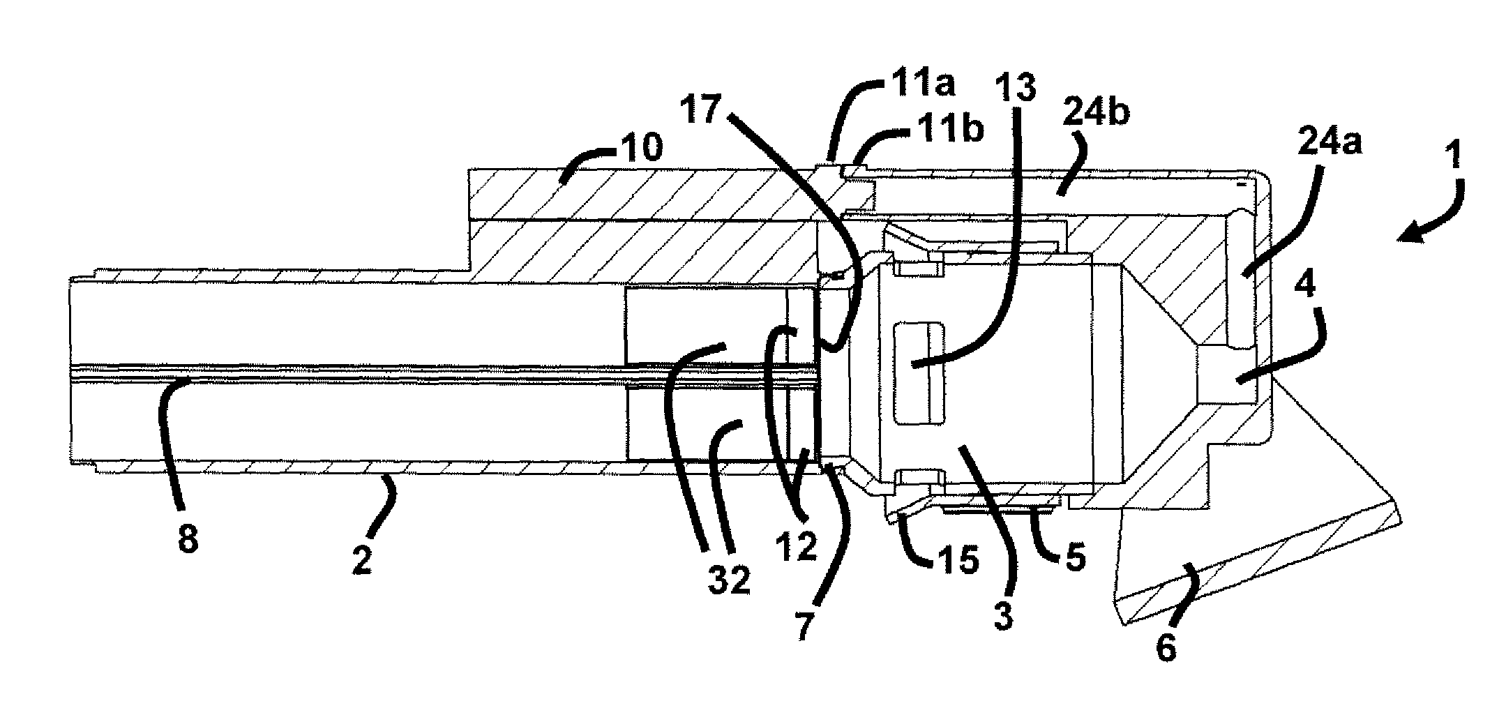
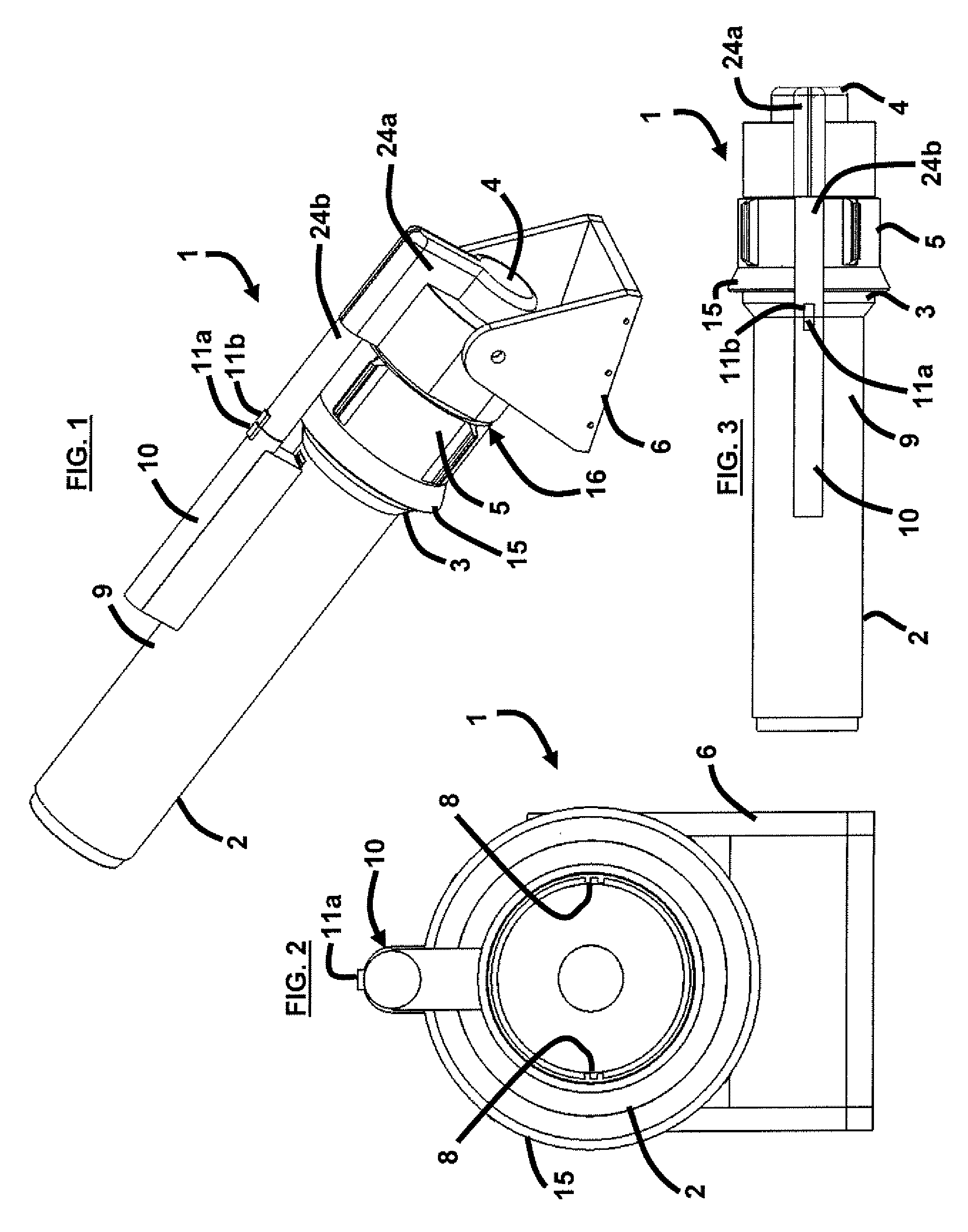
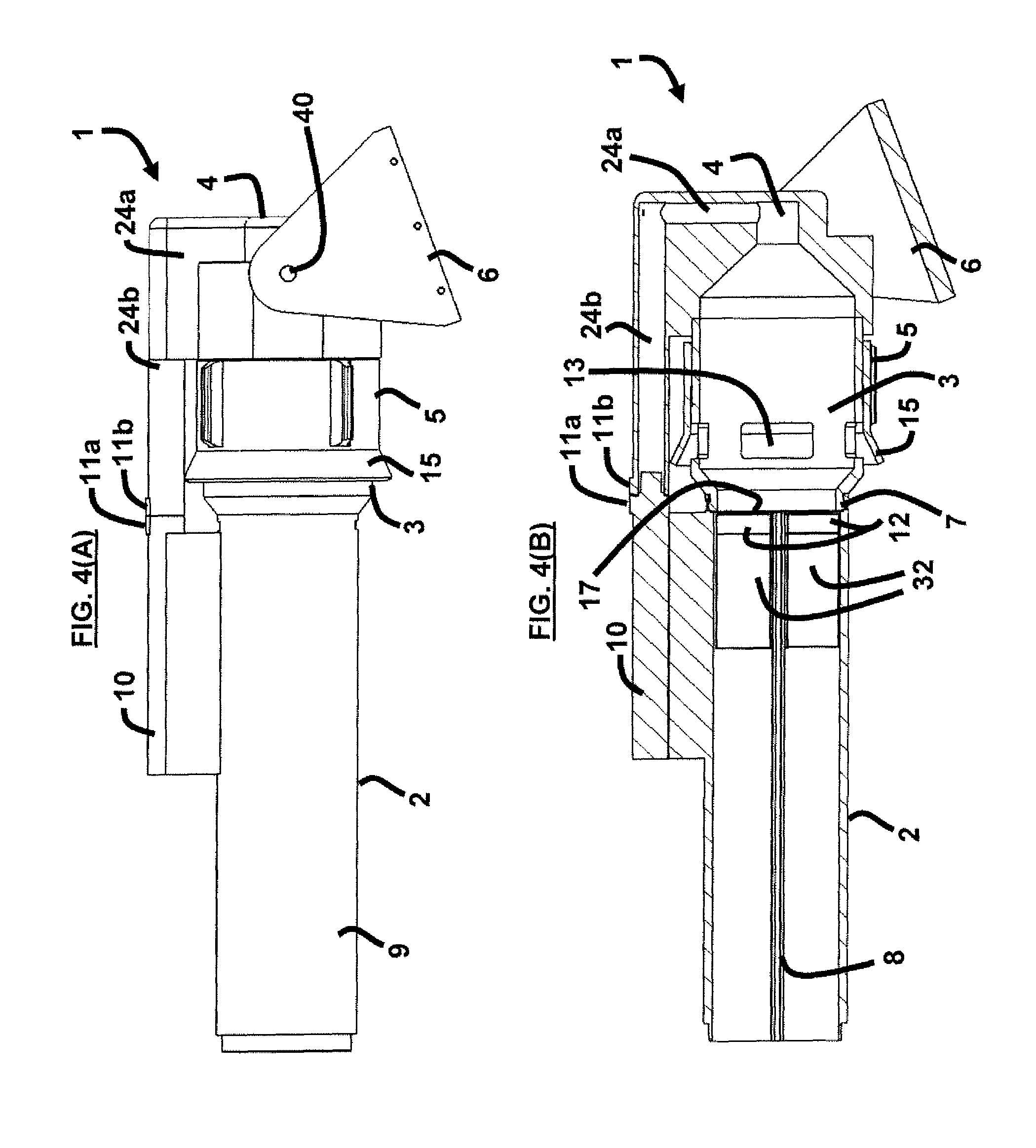
[0008]Preferably, the gas generator utilizes approximately 24Vdc of external electrical power to initiate functioning of the gas generator. Moreover, the pressure chamber may comprise a plurality of interconnected sections adapted to vent propulsion gases created by the gas generator upon launch of the projectile. Additionally, the barrel, the projectile, the gas generator, and the pusher cup are preferably expendable after each launch of the projectile. Furthermore, the vent sleeve may comprise a gas deflector adapted to redirect the vented propulsion gases forward and away from a user standing behind the barrel. Also, the pusher cup preferably has a higher aerodynamic drag and lower inertia than the projectile, wherein as the projectile and the pusher cup exit the barrel, the higher aerodynamic drag and lower inertia of the pusher cup causes a rapid deceleration and separation of the pusher cup from the projectile, thereby allowing the projectile to continue a ballistic flight path prior to transition to a self-propelled flight.
[0011]Preferably, the pre-packaging of the barrel to include the projectile, the pusher cup, and the gas generator allows for a repeatable launch operation comprising launching the projectile; and replacing of a spent barrel with a new pre-packaged barrel comprising a new projectile, a new pusher cup, and a new gas generator. Preferably, the gas generator utilizes approximately 24Vdc of external electrical power to initiate functioning of the gas generator.

Problems solved by technology

Typical launchers used for UAVs are generally large, cumbersome, or costly to use, and sometimes require multiple people to operate, require special handling for proper deployment, and often require hand assembly of the UAV.

Method used


Image

  • Gas generator launcher for small unmanned aerial vehicles (UAVs)
  • Gas generator launcher for small unmanned aerial vehicles (UAVs)
  • Gas generator launcher for small unmanned aerial vehicles (UAVs)

Examples


Embodiment Construction

[0035]The embodiments herein and the various features and advantageous details thereof are explained more fully with reference to the non-limiting embodiments that are illustrated in the accompanying drawings and detailed in the following description. Descriptions of well-known components and processing techniques are omitted so as to not unnecessarily obscure the embodiments herein. The examples used herein are intended merely to facilitate an understanding of ways in which the embodiments herein may be practiced and to further enable those of skill in the art to practice the embodiments herein. Accordingly, the examples should not be construed as limiting the scope of the embodiments herein.

[0036]As mentioned, there remains a need for a novel weapons launcher for small UAVs capable of being used by one person in a rapid, simple, and cost effective manner. The embodiments herein achieve this by providing a compact, easy-to-use, and cost-effective gas generator launcher for small UA...


PUM


Abstract

The launching of an unmanned projectile includes pre-packaging a barrel with a projectile, a pusher cup, and a gas generator. The gas generator generates gas to propel the projectile out of the barrel. A pressure chamber increases a pressure of the gas in the barrel. The pressure chamber comprises a front body portion connected to the gas generator; an aft body portion connected to the front body portion and the gas generator; and a vent sleeve positioned around the front body portion and adapted to provide an aperture through which the gas exits the barrel in order to control a level of gas pressure in the barrel. A triggering of the gas generator causes the pusher cup to push the projectile out of the barrel at a predetermined launch velocity in order to attain a predetermined self-propelled flight trajectory, wherein the triggering causes the pusher cup to exit the barrel.

Description

CROSS REFERENCE TO RELATED APPLICATION[0001]This application claims the benefit of U.S. Provisional Patent Application No. 60 / 846,592 and entitled “Gas Generator Launcher for Small Unmanned Aerial Vehicles (UAVs),” filed on Sep. 22, 2006, the complete disclosure of which in its entirety is herein incorporated by reference.GOVERNMENT INTEREST[0002]The embodiments described herein may be manufactured, used, and / or licensed by or for the United States Government without the payments of royalties thereon.BACKGROUND[0003]1. Technical Field[0004]The embodiments herein generally relate to weapon deployment systems, and, more particularly, to weapon deployment systems used for small unmanned aerial vehicles (UAVs).[0005]2. Description of the Related Art[0006]UAVs are typically used in military operations such as for surveillance. Typical launchers used for UAVs are generally large, cumbersome, or costly to use, and sometimes require multiple people to operate, require special handling for p...

Claims


Application Information

Patent Timeline
Patent Type & Authority Patents(United States)
IPC IPC(8): F41A1/04
CPCB64F1/04F41F1/00F41B11/62F41A21/18B64C2201/084B64U70/70
Inventor NAIR, MICHAEL L.CONDON, JOHN A.
Owner ARMY UNITED STATES OF AMERICA AS REPRESENTED BY THE SECREATRY OF THE
Learn More