Methods and systems for inspection of a specimen using different inspection parameters

a specimen and inspection system technology, applied in the field of methods and systems for specimen inspection using different inspection parameters, can solve the problems of not excellent sources of deep uv, the power drop of hg and hgxe sources, and the high cost of such sources, so as to enhance the defect detection properties

Active Publication Date: 2010-06-15
KLA TENCOR TECH CORP
View PDF37 Cites 6 Cited by
  • Summary
  • Abstract
  • Description
  • Claims
  • Application Information

AI Technical Summary

Benefits of technology

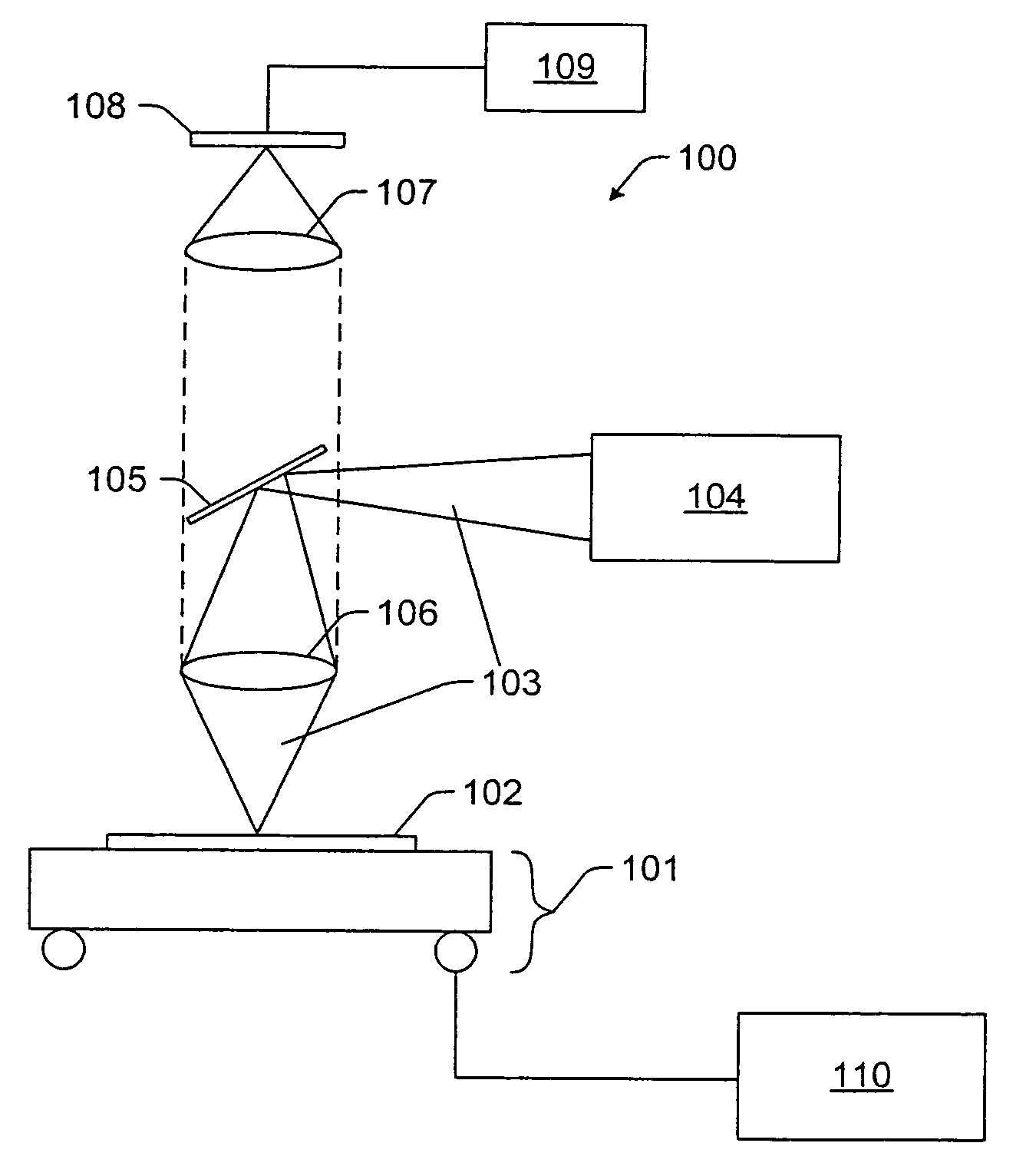
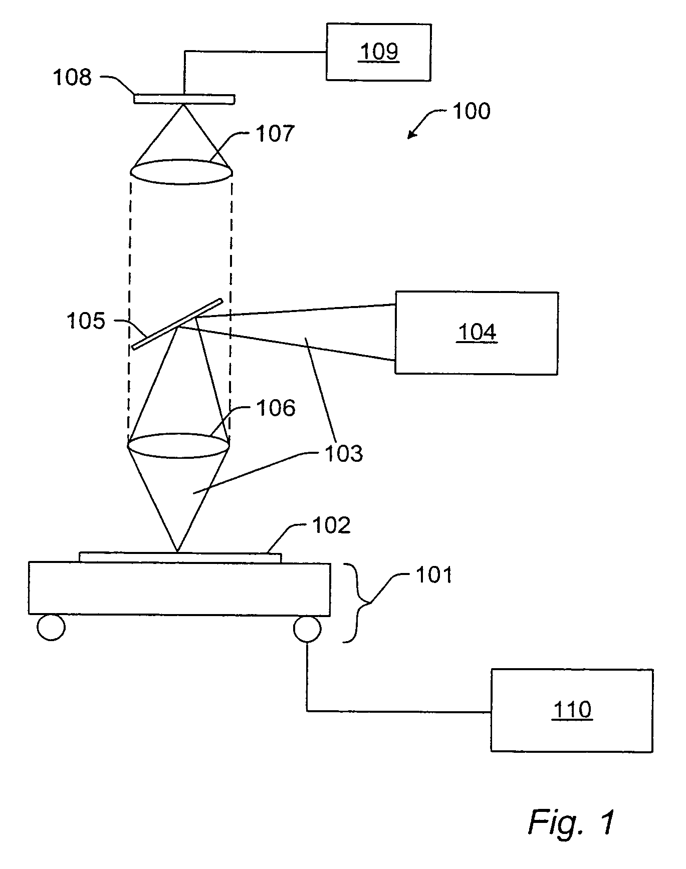
[0013]In accordance with the principles of the present invention, an apparatus and method for inspecting a surface are disclosed. In particular, the method and apparatus are capable of inspecting a surface in two (or more) optical regimes thereby enhancing the defect detection properties of such method and apparatus.

Problems solved by technology

Because the power of Hg and HgXe sources drops off rather dramatically, below 300 nanometers (nm) they are not excellent sources of deep UV (e.g., wavelengths below about 300 nm) illumination.
Due to the rather high cost of such sources (especially, the laser sources), no known inspection tools or methods have implemented two (or more) sources to inspect surfaces.
Although existing inspection machines and processes accomplish their designed purposes reasonably well, they have some limitations.

Method used


Image

  • Methods and systems for inspection of a specimen using different inspection parameters
  • Methods and systems for inspection of a specimen using different inspection parameters
  • Methods and systems for inspection of a specimen using different inspection parameters

Examples


Embodiment Construction

[0052]The inventor has discovered that increasing resolution in an inspection tool does not necessarily correlate to increased sensitivity to defects. In fact, illuminated substrates demonstrate a number of heretofore unappreciated optical properties which can be advantageously exploited by embodiments of the invention in order to achieve high signal-to-noise ratios and increased sensitivity to defects. The inventor has discovered that illuminating an object with more than one frequency of light can actually yield better defect detection results than simply employing the highest resolution system. Semiconductor substrates, being constructed of many layers of different materials, demonstrate a complex array of optical properties which have made the detection of defects in the substrates a difficult process.

[0053]However, the inventor has discovered methods of exploiting these differing material properties to increase the sensitivity of defect detection. As used herein, the term “surf...


PUM

PropertyMeasurementUnit
wavelengthaaaaaaaaaa
near ultraviolet wavelengthsaaaaaaaaaa
wavelengthsaaaaaaaaaa

Abstract

Methods and systems for inspection of a specimen using different parameters are provided. One computer-implemented method includes determining optimal parameters for inspection based on selected defects. This method also includes setting parameters of an inspection system at the optimal parameters prior to inspection. Another method for inspecting a specimen includes illuminating the specimen with light having a wavelength below about 350 nm and with light having a wavelength above about 350 nm. The method also includes processing signals representative of light collected from the specimen to detect defects or process variations on the specimen. One system configured to inspect a specimen includes a first optical subsystem coupled to a broadband light source and a second optical subsystem coupled to a laser. The system also includes a third optical subsystem configured to couple light from the first and second optical subsystems to an objective, which focuses the light onto the specimen.

Description

PRIORITY CLAIM[0001]This application claims priority to U.S. Provisional Application No. 60 / 500,174 entitled “Methods and Systems for Inspection of a Specimen Using Different Inspection Parameters,” filed Sep. 4, 2003, which is incorporated by reference as if fully set forth herein.STATEMENT REGARDING FEDERALLY SPONSORED RESEARCH OR DEVELOPMENT[0002]The United States Government may have certain rights to portions of the inventions described herein as provided for by the terms of Cooperative Agreement No. 70NANB0H3038 awarded by the National Institute of Standards & Technology (NIST).BACKGROUND OF THE INVENTION[0003]1. Field of the Invention[0004]The present invention generally relates to methods and systems for inspection of a specimen using different inspection parameters. Certain embodiments relate to computer-implemented methods for determining optimal parameters for inspection of a specimen based on defects selected for detection. Other embodiments relate to methods and systems ...

Claims


Application Information

Patent Timeline
Patent Type & Authority Patents(United States)
IPC IPC(8): G01N21/00G01N21/95
CPCG01N21/9501G01N21/8806
Inventor LANGE, STEVE R.MARELLA, PAUL FRANKCEGLIO, NATHWANG, SHIOW-HWEIFU, TAO-YI
Owner KLA TENCOR TECH CORP
Why Eureka
Try Eureka