
Focus detection optical system having a plurality of focus detection areas, and imaging apparatus incorporating the same

a technology of optical system and focus detection area, which is applied in the direction of exposure control, printers, camera focusing arrangement, etc., can solve the problems of affecting aberration and likely increase in the incidence angle of the layout, so as to increase the degree of flexibility in the selection of focus detection areas, prevent a decrease in the quantity of light, and increase the degree of flexibility

Inactive Publication Date: 2010-06-15
OM DIGITAL SOLUTIONS CORP
View PDF4 Cites 2 Cited by
  • Summary
  • Abstract
  • Description
  • Claims
  • Application Information

AI Technical Summary

Benefits of technology

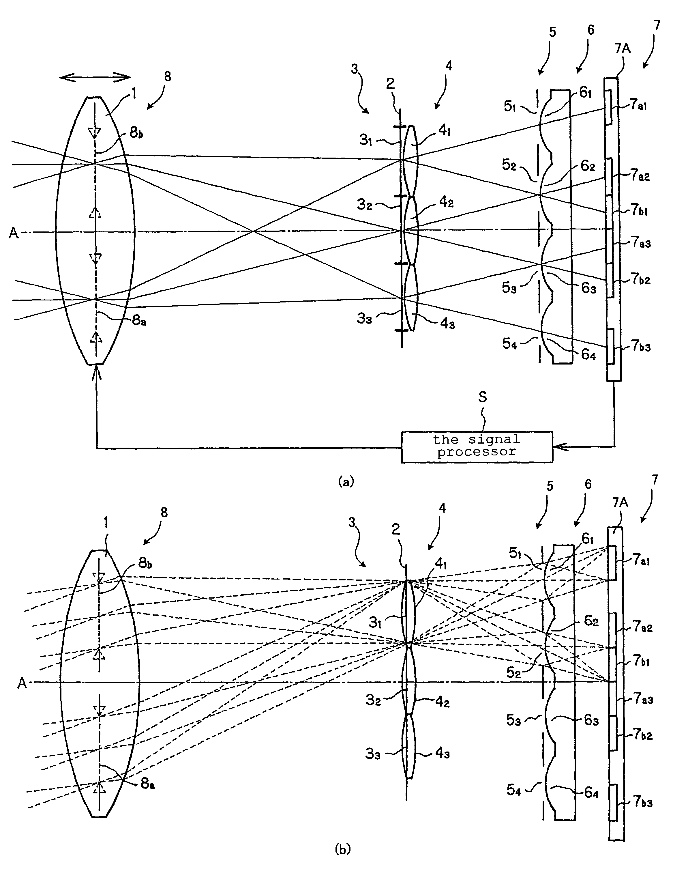
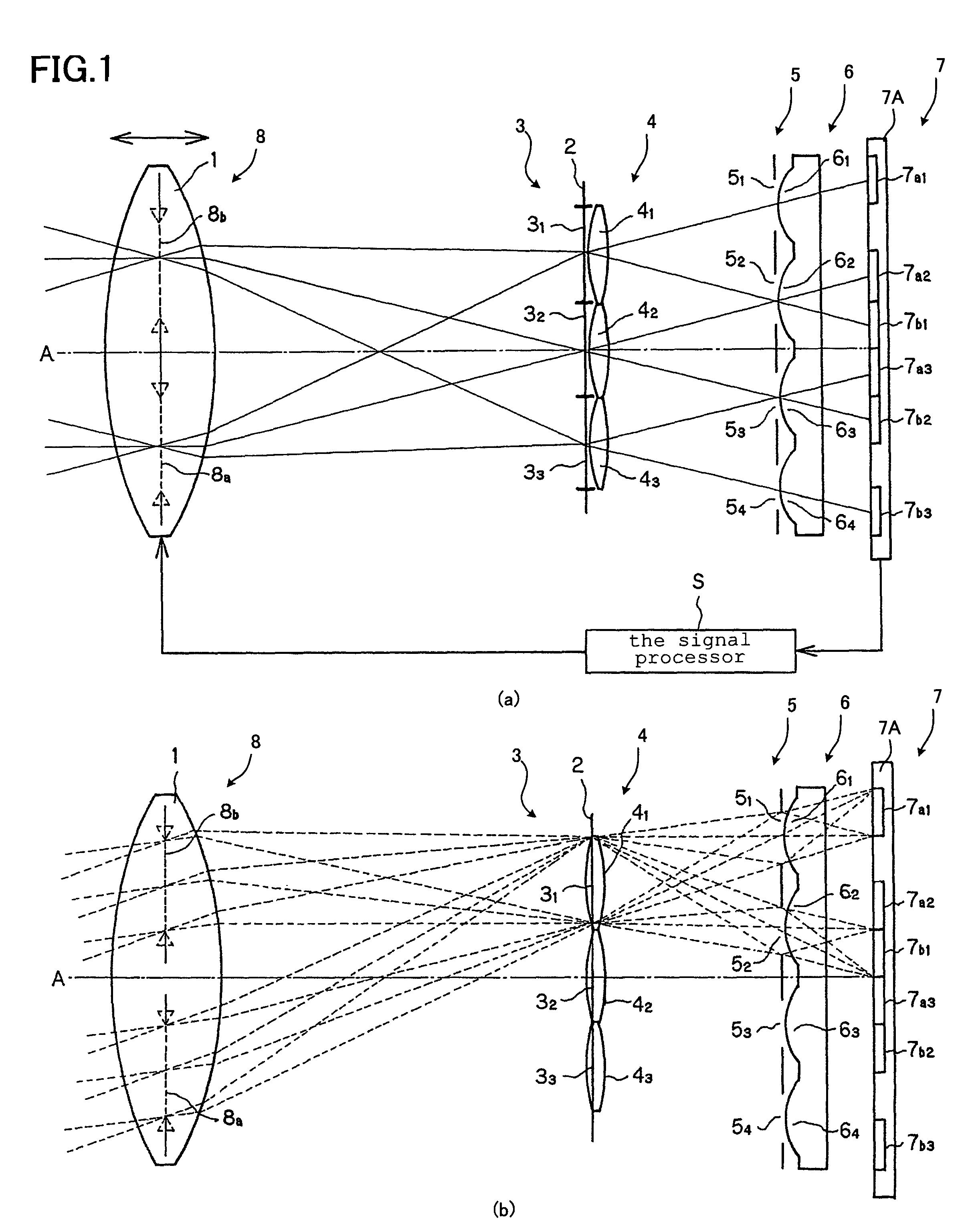
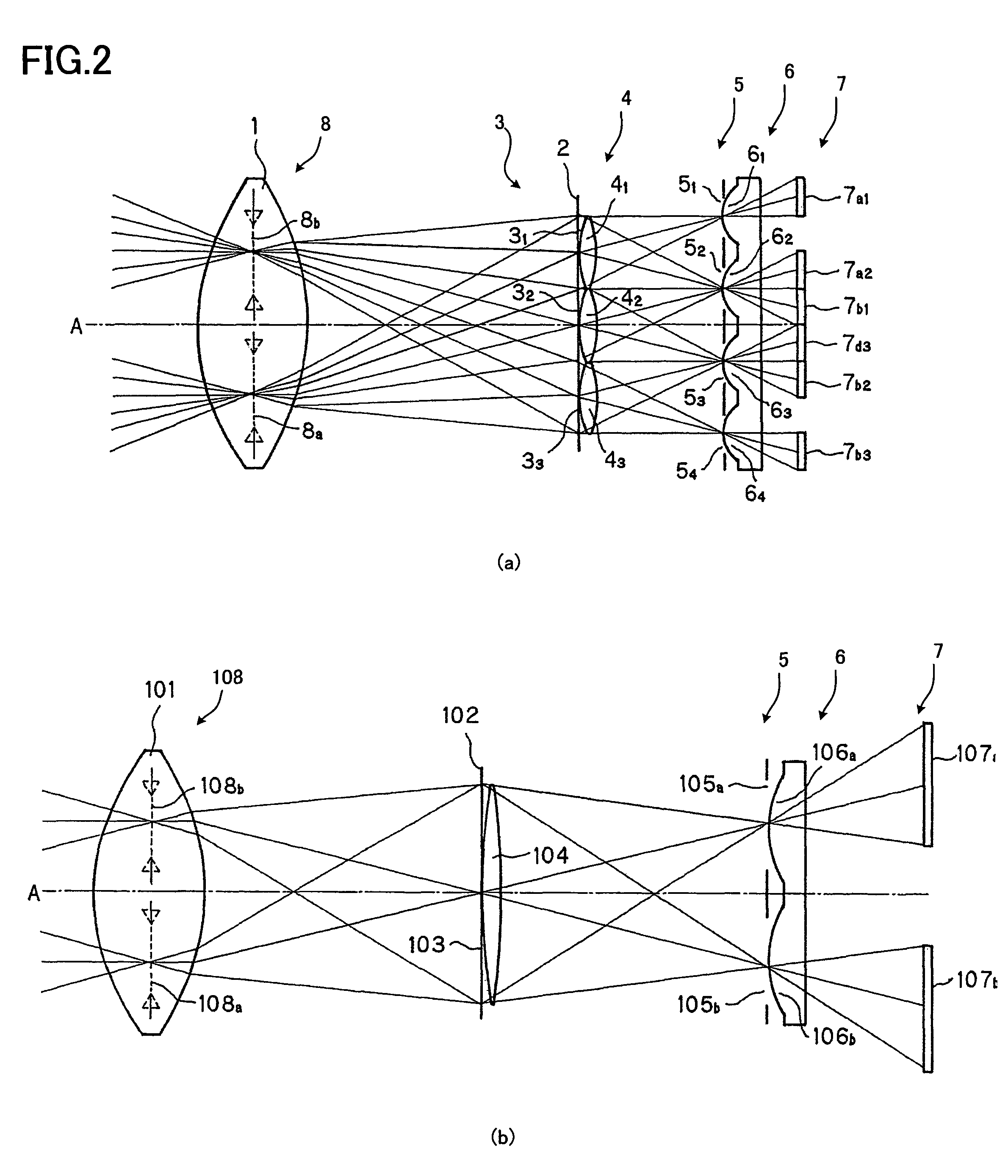
[0014]Thus, each of the n adjoining or intersecting focus detection areas may be set up with a pair of adjoining openings and a pair of adjoining re-imaging lenses. And the respective re-imaging lenses being adjacent to each other renders it easy to make the angle of incidence of light rays on them small and keep aberrations in check, even when the distance between the focus detection area and the re-imaging lens is shorter.
[0051]Further, the invention provides an imaging apparatus, comprising an imaging device adapted to take an image formed by a taking lens, a focus detection optical system, and a reflective member adapted to reflect a light beam from said taking lens and guide said light beam to a predetermined imaging plane, characterized in that said reflective member retracts out of a taking optical path when the image is taken by said imaging device. By the retraction of the reflective member when an image is taken by the imaging device, it is thus possible to provided an imaging apparatus that prevents a decrease in the quantity of light of an image taken by the imaging device.

Problems solved by technology

Such an optical layout is likely to have an increased angle of incidence to the re-imaging lenses and so be affected by aberrations.
With such an arrangement, an attempt to increase focus detection area size would increase the angle of incidence on each re-imaging lens in the re-imaging lens group, and so tend to produce aberrations.

Method used


Image

  • Focus detection optical system having a plurality of focus detection areas, and imaging apparatus incorporating the same
  • Focus detection optical system having a plurality of focus detection areas, and imaging apparatus incorporating the same
  • Focus detection optical system having a plurality of focus detection areas, and imaging apparatus incorporating the same

Examples


second embodiment

[0136]FIG. 5 is illustrative of the second embodiment wherein the embodiment of FIG. 1 is modified such that the range-finding area is extended crosswise in two directions so that phase difference information for implementing focus detection is also used in two directions. The layout for the center re-imaging lens 6 has the merit of easily extending the range-finding area crosswise.

[0137]In the embodiment shown in FIG. 5, a taking lens 21, and two sets of virtual areas (a pair of 28a and 28b, and a pair of 28c and 28d) are supposed to be provided. One set is supposed to comprise 28a and 28b and another 28c and 28d.

[0138]One set of virtual areas and another set of virtual areas are arranged in different directions (with 28a and 28b in the horizontal and 28c and 28d in the vertical). Field apertures 2321, 2322, 2323, 2312 and 2332 that define openings in five field stops for focus detection areas are supposed to be located near a predetermined imaging plane 22 (not shown) equivalent ...

third embodiment

[0163]FIG. 7 is illustrative of the invention wherein such focus detection systems as shown in FIG. 3 are arranged in rows and columns. In FIG. 7, field apertures 43 that are openings in the field stops in a focus detection area, re-imaging lenses 46 and an array of light receptor elements 47 are schematically depicted.

[0164]Briefly, there are such virtual areas 48a, 48b, 48c and 48d as in FIG. 6 provided, and there are field apertures 43ij arrayed on m matrices in the direction that the virtual areas 48a and 48b are lined up and n matrices in the direction that the virtual areas 48c and 48d are lined up (l43, there are condenser lens 44ij (l43.

[0165]It is here noted that m and n will increase at an increment of 1 in the lined-up direction. Each field aperture 43 is just about the detection of a phase difference in the vertical and horizontal directions, and for this, use may be made of an crosswise aperture wherein long focus detection areas in the vertical and horizontal direction...


PUM


Abstract

The invention relates to a focus detection optical system used with the so-called autofocus (AF) system mounted on single-lens reflex cameras (SLRs) or the like, and an imaging apparatus incorporating it. The focus detection optical system comprises at least n focus detection areas that are adjacent to or intersect each other on a predetermined imaging plane, where n≧2. A re-imaging lens group comprises n+1 re-imaging lenses, A (n−1)th re-imaging lens and an nth re-imaging lens are a pair of re-imaging lenses that correspond to a (n−1)th focus detection area and are adjacent to each other. An nth re-imaging lens and a (n+1)th re-imaging lens are a pair of re-imaging lenses that correspond to the nth focus detection area and are adjacent to each other. The (n−1)th re-imaging lens and (n+1)th re-imaging lens are located at different positions.

Description

[0001]This application claims benefit of Japanese Application No. 2007-128782 filed in Japan on May, 15, 2007, the contents of which are incorporated by this reference.BACKGROUND OF THE INVENTION[0002]The present invention relates generally to a focus detection system used with the so-called phase difference type autofocus (AF) system mounted on single-lens reflex cameras (SLRs) or the like, and an imaging apparatus incorporating it. More particularly, the invention is concerned with a focus detection optical system that, with a taking lens defocused theoretically, enables a defocus direction and a defocus quantity to be so figured out that the taking lens can be more quickly placed in an in-focus state than achieved with the so-called contrast method, and an imaging apparatus incorporating it.[0003]So far, there has been a system comprising a taking lens for projecting a subject onto an imaging plane, a means for splitting or selecting an optical path from the taking lens to the im...

Claims


Application Information

Patent Timeline
Patent Type & Authority Patents(United States)
IPC IPC(8): G02B7/04G02B7/28
CPCG02B7/346H04N5/23212G03B13/36G03B3/00
Inventor GOTO, HISASHI
Owner OM DIGITAL SOLUTIONS CORP
Learn More