
Electrosurgical system with uniformly enhanced electric field and minimal collateral damage

a surgical system and electric field technology, applied in the field of electrosurgical devices, can solve the problems of reducing unable to penetrate the electrode into the tissue, and causing shallow cuts on the surface, so as to reduce the effect of electroporation-related tissue damage and effective smoothing

Active Publication Date: 2010-06-15
THE BOARD OF TRUSTEES OF THE LELAND STANFORD JUNIOR UNIV
View PDF285 Cites 80 Cited by
  • Summary
  • Abstract
  • Description
  • Claims
  • Application Information

AI Technical Summary

Benefits of technology

This approach enables uniform tissue cutting along an extensive cutting zone with reduced mechanical damage and increased cutting efficiency, as the blade electrodes provide mechanical strength and visibility, while the tailored electrical pulses ensure effective energy deposition and reduced collateral damage.

Problems solved by technology

An inlaid cylindrical electrode cannot penetrate into tissue and thus can only produce shallow cuts on its surface.
In addition, cavitation bubbles accompanying each pulse create substantial collateral damage in tissue during their growth and collapse phases.
Reduction in pulse energy helps to reduce the mechanical damage, but may also lead to decreased cutting depth.
However, this approach is limited by the mechanical strength of the thin wire and its visibility.
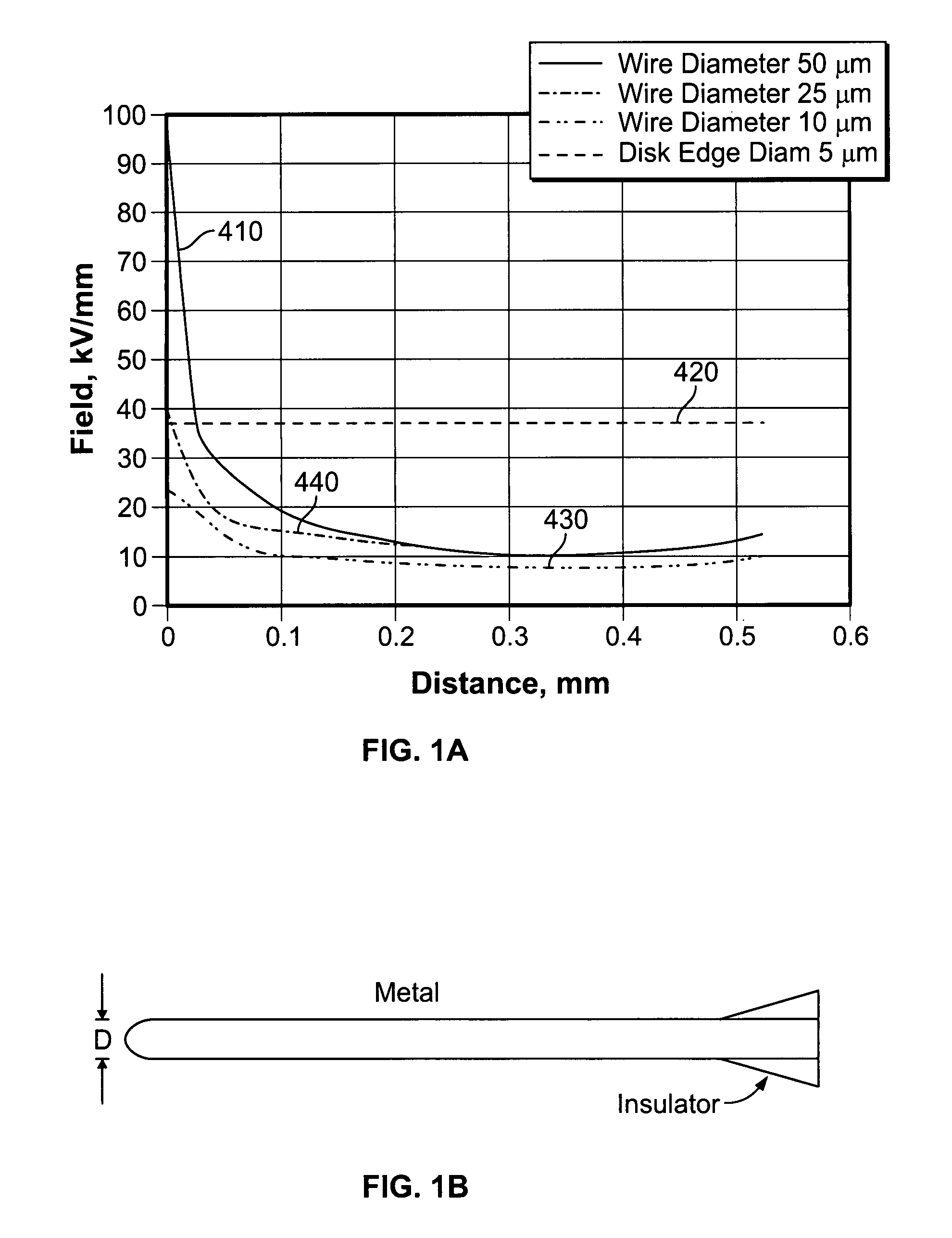
In addition, the problem of non-uniform distribution of electric field along the electrode, and particularly, enhancement at the apex remains.
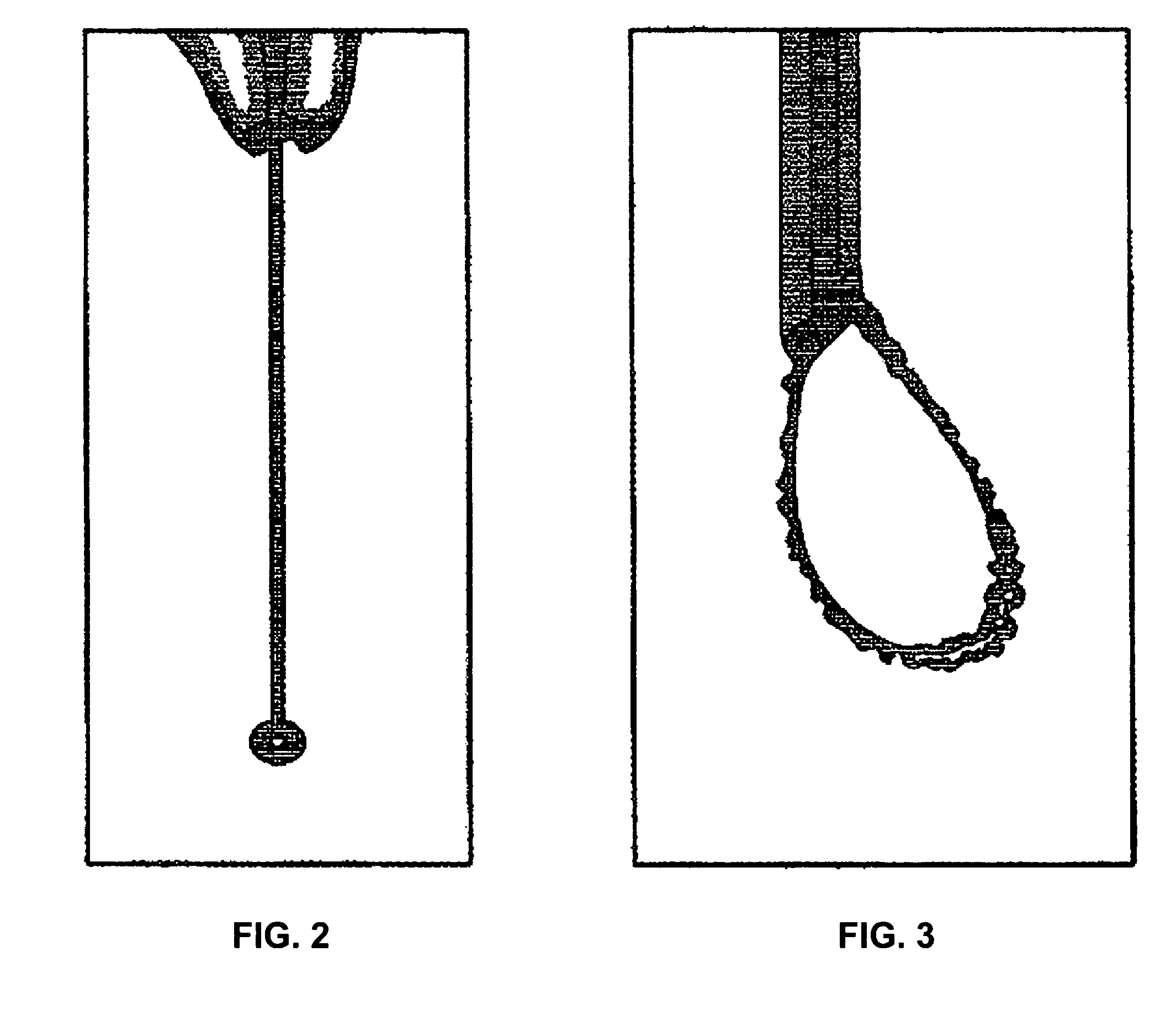
Thus, ionization and vaporization on such an electrode will always begin and be dominant at locations of enhanced field strength, leading to uneven cutting and excessive damage in front of these singular points, as shown in FIG. 2.
For example, a thin wire is very weak and flexible and is thus inapplicable to manipulation of tissue.
In addition, wires thinner than 25 microns are barely seen under a conventional surgical microscope, and this makes their use even more difficult.
An additional problem with the application of thin wires is that erosion of thin wires greatly limits their lifetime.
Erosion of the blade may occur because of electrochemical or thermal reactions on the electrode, and may be a problem for existing electrosurgical electrodes, including electrosurgical blades.
During electrosurgical cutting with plasma, the plasma formed along the exposed electrode surface may result in localized high temperatures that may differentially etch the electrode and the adjacent insulation.
The result is to change the geometry of the cutting electrode, which may be particularly undesirable, and may affect the ability to cut with the electrode, as well as the energy required to drive the electrode.
This results in higher power dissipation which may lead to increase generation of heat in the tissue volume, formation of excess gas (bubbles), an increase in the zone of electroporation damage, and unstable generation of plasma during surgery.
This problem may be a result of insulation materials having a low-melting and / or vaporization point (e.g., volatile insulators such as plastics).
However, a parallel problem may result when the insulation layer is too resistant to erosion, as shown in FIG. 10C.
As the conductive metal erodes from the insulation, a gap is formed between the metal, resulting in a gap between the conductive metal and the surrounding material.
At some point this gap may prevent cutting of tissue by the electrode, either because of physical separation from the tissue, or because the voltage will be insufficient for vaporization and ionization, terminating the electric discharge.

Method used


Image

  • Electrosurgical system with uniformly enhanced electric field and minimal collateral damage
  • Electrosurgical system with uniformly enhanced electric field and minimal collateral damage
  • Electrosurgical system with uniformly enhanced electric field and minimal collateral damage

Examples


Embodiment Construction

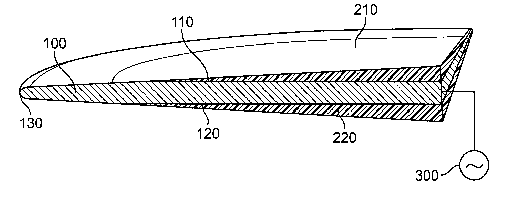
[0056]Referring now to the drawings, where similar elements are numbered the same, FIG. 4A depicts an electrically conductive blade 100 having a first blade surface 110, a second blade surface 120, and a blade edge 130. In practice, the blade edge 130 is somewhat rounded, the edge radius of curvature 140 being shown in the magnified view of FIG. 4B. A first insulator 210 is affixed to the first blade surface 110. Similarly, a second insulator 220 is affixed to the second blade surface 120. To complete an electrosurgical cutting system, a source of pulsed electrical energy 300 is coupled to the blade 100. The other terminal from the source of pulsed electrical energy 300 is connected to a return electrode (not shown) immersed in the medium in which the blade 100 is inserted.

[0057]At any position on the blade 100, the blade thickness is the smallest distance between the first blade surface 110 and the second blade surface 120. In some embodiments, in the region adjacent the blade edge...


PUM


Abstract

The present invention is directed towards an electrosurgical cutting system. The system comprises an electrically conductive blade, having an uninsulated cutting edge that is surrounded by an insulator. A source of pulsed electrical energy may be coupled to the electrically conductive blade to provide a substantially uniform and highly enhanced electric field along a cutting portion of the blade edge. The blade may have a uniform rate of erosion during use, so that both the conductive metal edge and the surrounding insulation layer erode at approximately the same rate. Also described are methods of fabricating insulated cutting electrodes, particularly blade electrodes.

Description

STATEMENT REGARDING FEDERALLY SPONSORED RESEARCH OR DEVELOPMENT[0001]This invention was supported by the National Institutes of Health under contract number R01 EY 12888. The government has certain rights in this invention.FIELD OF THE INVENTION[0002]The present invention relates generally to an electro-surgical device, and in particular, to the design of efficient electro-surgical probes and waveforms for pulsed plasma-mediated cutting, fragmentation, and evaporation of biological tissue in fluid media.BACKGROUND OF THE INVENTION[0003]Plasma-mediated cutting of biological tissue with sub-microsecond pulses of high voltage is described in the patent of Palanker (U.S. Pat. No. 6,135,998), herein incorporated by reference in its entirety. Dissection of tissue based on explosive vaporization by short (under a few microseconds) pulses of high voltage is described in the patent of Lewis et al. (U.S. Pat. No. 6,352,535). In these applications, an inlaid cylindrical electrode (i.e., a wire...

Claims


Application Information

Patent Timeline
Patent Type & Authority Patents(United States)
IPC IPC(8): A61B18/14
CPCA61B18/1402A61B2018/1407A61B2018/00083
Inventor PALANKER, DANIEL V.VANKOV, ALEXANDER B.
Owner THE BOARD OF TRUSTEES OF THE LELAND STANFORD JUNIOR UNIV
Learn More