Gain correction for a CT system

a ct system and gain correction technology, applied in the field of xray imaging, can solve problems such as errors relating to differences between reconstructed values and ideal values generated, and achieve the effect of reducing errors

Active Publication Date: 2010-06-08
THE BOARD OF TRUSTEES OF THE LELAND STANFORD JUNIOR UNIV
View PDF3 Cites 6 Cited by
  • Summary
  • Abstract
  • Description
  • Claims
  • Application Information

AI Technical Summary

Benefits of technology

[0002]In accordance with the invention, a method for imaging unknown objects in a computed tomography (CT) system, comprising determining ray gain for a known object is provided. A CT reconstruction is performed with the known object to obtain reconstructed values. Ideal values are obtained for pixels of the known object. An error related to a difference between the reconstructed values and the ideal values is generated. A ray gain is estimated that reduces the error.

Problems solved by technology

An error related to a difference between the reconstructed values and the ideal values is generated.

Method used


Image

  • Gain correction for a CT system
  • Gain correction for a CT system
  • Gain correction for a CT system

Examples


Embodiment Construction

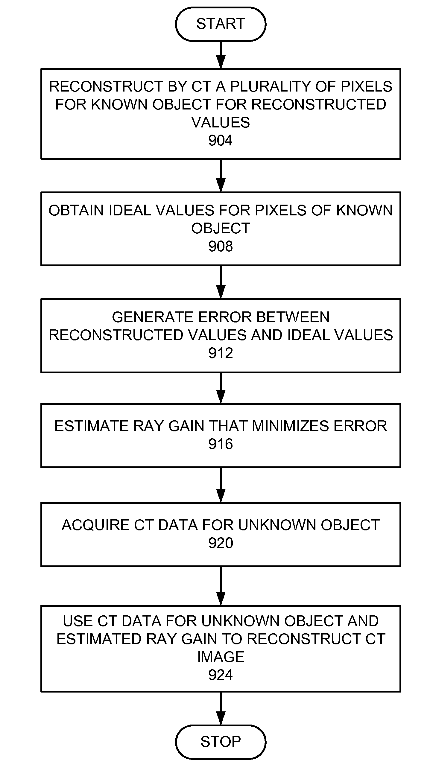
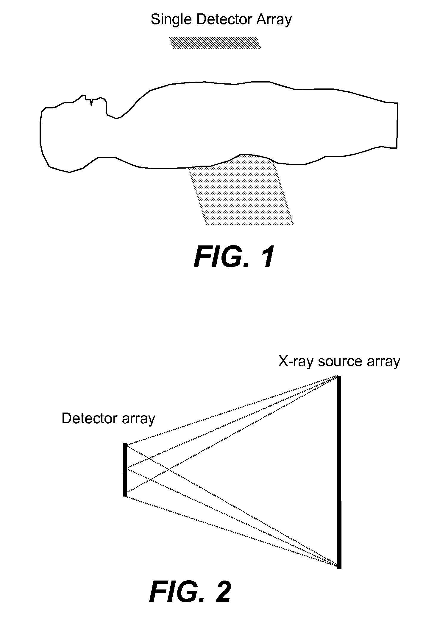
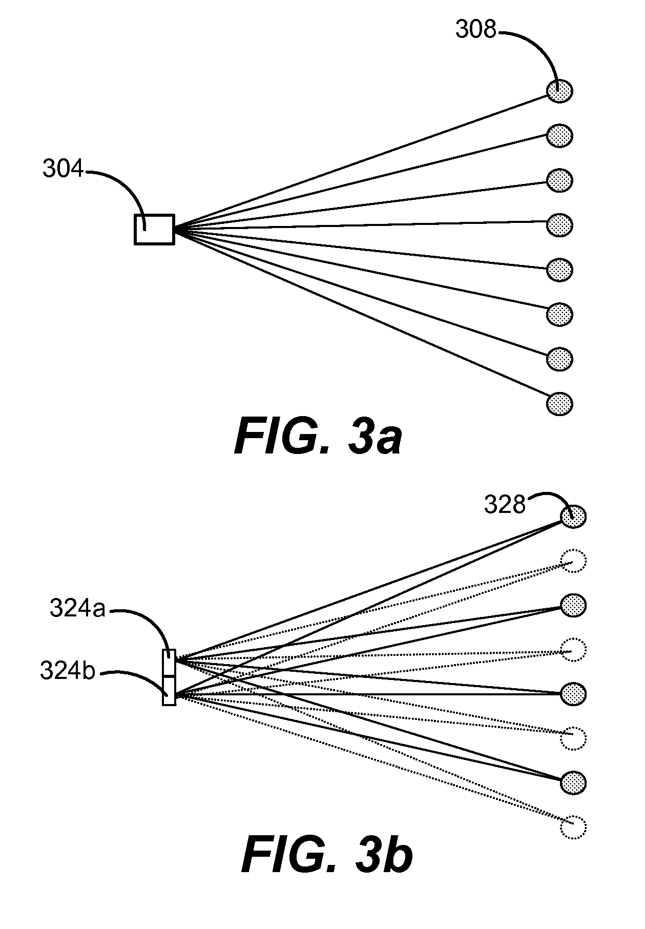
[0019]An inverse geometry volumetric CT (IGCT) system uses a large source array opposite a smaller detector array. 2D IGCT reconstruction may be performed by using gridding. One application of the present invention is 2D IGCT reconstruction without gridding. The IGCT raw data can be viewed as being composed of many fan beams, each with a detector at its focus. Each projection is undersampled but the missing samples are provided by other views. In order to get high spatial resolution, zeros are inserted between acquired projection samples in each fan beam, and reconstruction is performed using a direct fan beam reconstruction algorithm. Initial IGCT reconstruction results showed ringing artifacts caused by the fact that the rho samples in the ensemble of views are not equally spaced. An example of the invention provides a method for correcting the errors that reduces the artifacts to below one Hounsfield Unit.

[0020]An inverse geometry volumetric CT (IGCT) system uses a large-area sca...


PUM


Abstract

A method for imaging unknown objects in a computed tomography (CT) system, comprising determining ray gain for a known object is provided. A CT reconstruction is performed with the known object to obtain reconstructed values. Ideal values are obtained for pixels of the known object. An error related to a difference between the reconstructed values and the ideal values is generated. A ray gain is estimated that reduces the error.

Description

BACKGROUND OF THE INVENTION[0001]This invention relates generally to x-ray imaging including computed tomography (CT). More specifically the invention relates to a reconstruction algorithm for creating a CT image. Computed tomography (CT) is a medical technique for visualizing internal organs with high resolution. Both fan beams and cone beams of x-rays may be employed in CT.SUMMARY OF THE INVENTION[0002]In accordance with the invention, a method for imaging unknown objects in a computed tomography (CT) system, comprising determining ray gain for a known object is provided. A CT reconstruction is performed with the known object to obtain reconstructed values. Ideal values are obtained for pixels of the known object. An error related to a difference between the reconstructed values and the ideal values is generated. A ray gain is estimated that reduces the error.[0003]In another manifestation of the invention, a computed tomography (CT) system is provided. A detector array is provide...

Claims


Application Information

Patent Timeline
Patent Type & Authority Patents(United States)
IPC IPC(8): A61B6/00
CPCG06T11/005A61B6/032
Inventor BAEK, JONGDUKPELC, NORBERT J.
Owner THE BOARD OF TRUSTEES OF THE LELAND STANFORD JUNIOR UNIV
Why Eureka
Try Eureka