
Method and apparatus for multichannel signal limiting

a multi-channel, signal-limiting technology, applied in the direction of amplifier combinations, volume compression/expansion, instruments, etc., can solve the problems of reducing the signal information, changing the waveform shape, and inherently hard-limiting, so as to prevent clipping and prevent clipping

Inactive Publication Date: 2010-06-01
SONY CORP
View PDF19 Cites 46 Cited by
  • Summary
  • Abstract
  • Description
  • Claims
  • Application Information

AI Technical Summary

Benefits of technology

This approach prevents clipping across all channels without altering the relative amplitude relationships, thereby maintaining the integrity of the sound imaging and spatial representation in multichannel audio signals, and can be applied to various multichannel signal applications.

Problems solved by technology

Hard limiting may occur inherently, such as when the value of a signal exceeds the full-scale measurement range available for measuring the signal.
In any case, hard limiting typically “clips” a given waveform at the limit, which changes the waveform shape, forfeits signal information, and introduces signal non-linearity.
Not surprisingly, then, soft limiting represents the preferred approach in applications where the non-linearity that would be introduced by hard limiting is objectionable.
Soft limiting in audio applications prevents undesirable non-linearity in the audio signal, which would result in audible distortions.
Regardless of the underlying reason for imposing magnitude limits, the application of limiting control to a multichannel signal can be problematic.
With multichannel audio signals, altering the relative amplitudes among the channel signals causes unintended and oftentimes undesirable effects.
Other types of deleterious effects may arise in other multichannel signal limiting applications.

Method used


Image

  • Method and apparatus for multichannel signal limiting
  • Method and apparatus for multichannel signal limiting
  • Method and apparatus for multichannel signal limiting

Examples


Embodiment Construction

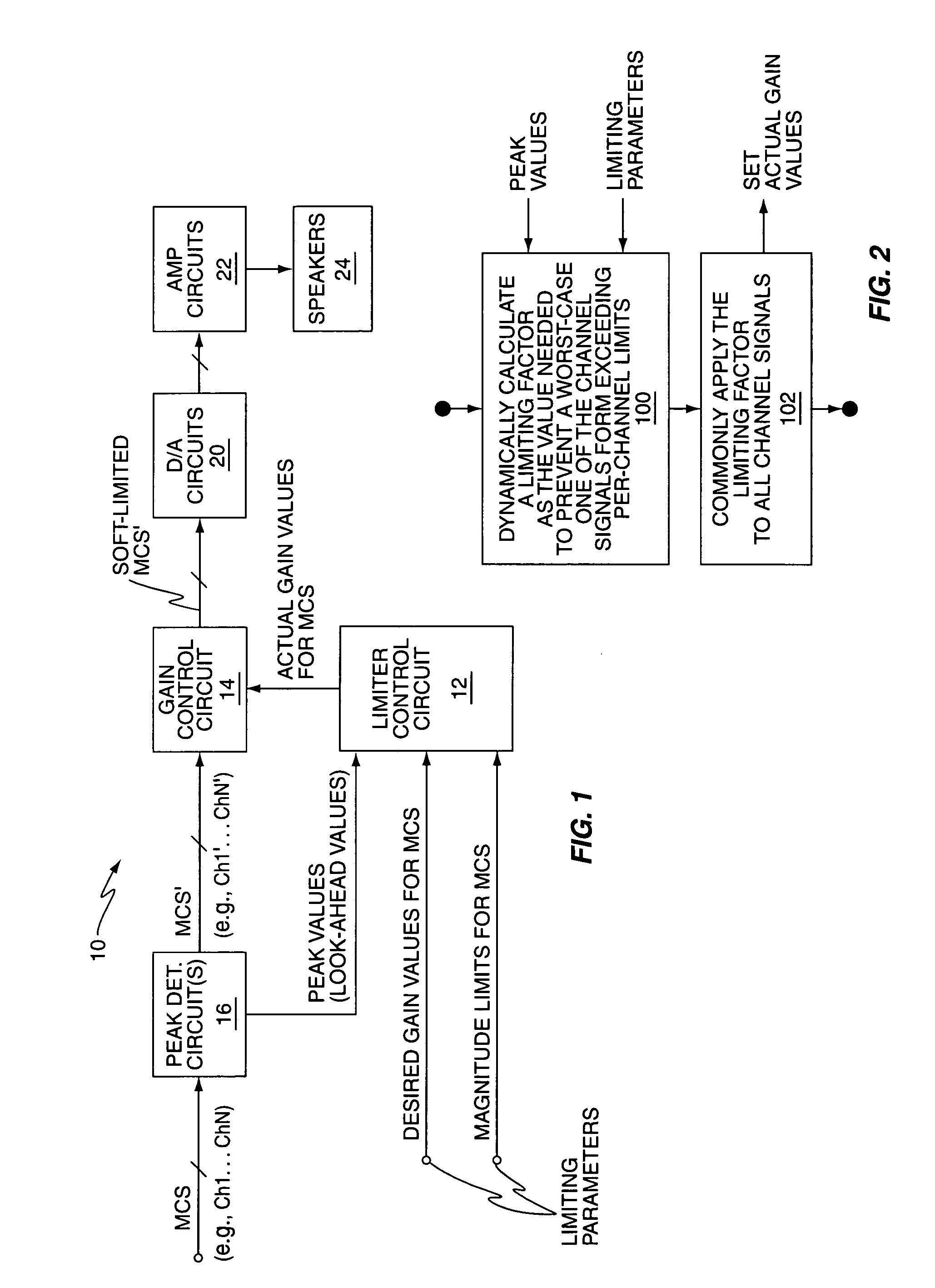
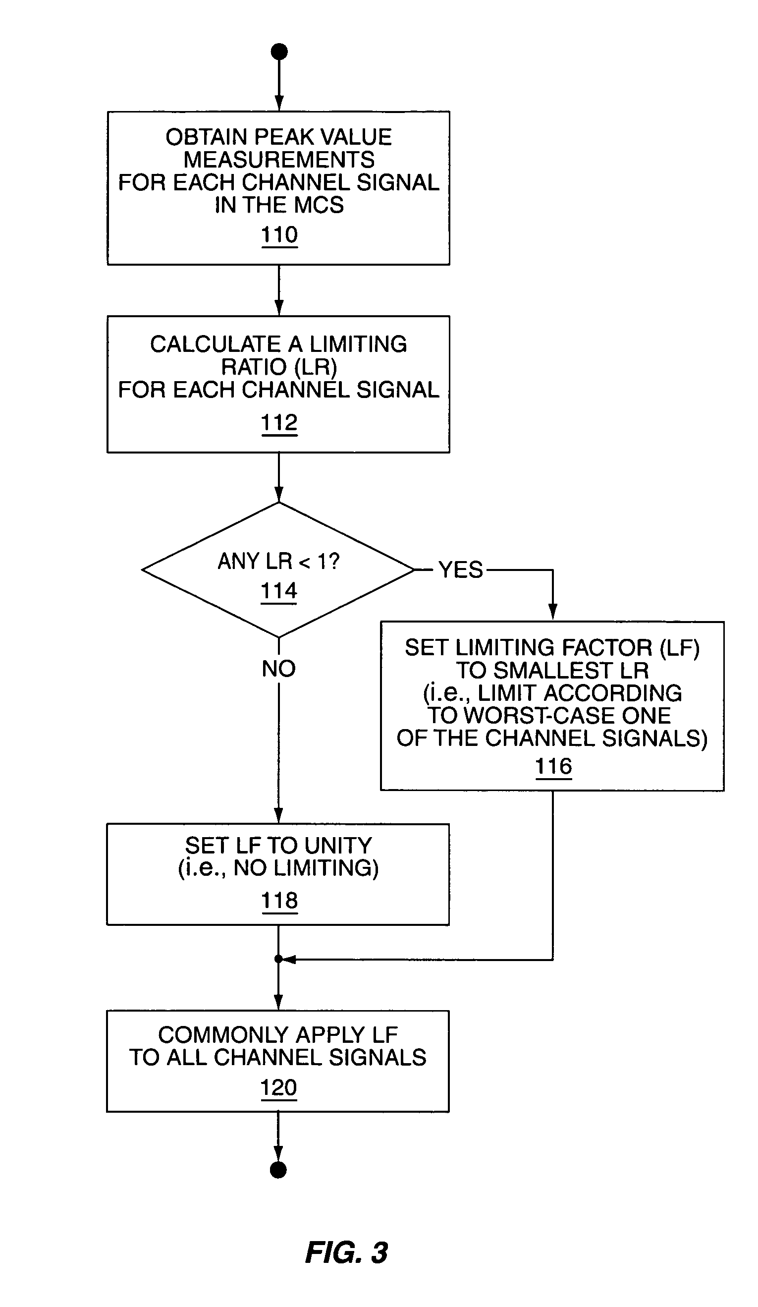
[0022]FIG. 1 functionally illustrates one embodiment of a multichannel limiter 10 that provides limiting control for multichannel signals, such as a multichannel audio signal comprising left and right channel signals, for example. In particular, the limiter 10 is configured to set a “limiting factor” dynamically to whatever value is needed to prevent any channel signal included in the multichannel signal from exceeding defined magnitude limits and commonly applying that limiting factor to all channel signals. In other words, the limiter 10 coordinates the gain reduction of all channel signals making up the multichannel signal to prevent any channel signal from clipping, while simultaneously preserving the relative gain and amplitude relationships among the channel signals.

[0023]The limiter 10 performs multichannel signal limiting based on the application of a common limiting factor even where the limiter parameters, e.g., the maximum magnitude limit, the desired channel gain, and th...


PUM


Abstract

A method and apparatus provide multichannel signal limiting to prevent any channel signal within a multichannel signal from exceeding defined limits, while still preserving the gain and / or amplitude relationships among the individual channel signals. A limiter is configured to calculate a limiting factor as the value needed to prevent a limit violation on the worst-case one of the channel signals, and then commonly apply that limiting factor to the gain control of all channel signals. Thus, the limiter may generate an actual gain value for each channel signal as the product of that channel signal's desired gain value and the current value of the limiting factor. Notably, in multichannel audio signal applications, coordinating gain control across the individual audio channels by use of the commonly applied limiting factor prevents undesirable spatial shifting of the soundstage, e.g., shifting of the stereo image.

Description

RELATED APPLICATIONS[0001]This application claims priority under 35 U.S.C. §119(e) from the U.S. provisional application Ser. No. 60 / 640,607 filed on 30 Dec. 2004 and entitled “Method and Apparatus for Multichannel Signal Limiting.” That provisional application is incorporated in its entirety herein by reference.BACKGROUND OF THE INVENTION[0002]The present invention generally relates to signal limiters used to prevent clipping or saturation, or to control the characteristics of a signal around some maximum amplitude, and particularly relates to multichannel limiters.[0003]Signal limiting represents a common safeguarding function that is employed in a wide variety of applications, in the analog, digital and acoustic domains. Signal limiting in its simplest form comprises limiting a given signal's amplitude at some maximum permissible value. Hard limiting, for example, imposes a hard limit on the peak signal amplitude permitted, with the hard limit typically set at the value needed to...

Claims


Application Information

Patent Timeline
Patent Type & Authority Patents(United States)
IPC IPC(8): H04B1/26G10L19/008G10L21/034
CPCH03F3/68H03G7/00H03F2200/435
Inventor ROMESBURG, ERIC DOUGLASGUSTAVSSON, STEFAN
Owner SONY CORP
Learn More