
Method and apparatus for space-time coding using lifting low density parity check codes in a wireless communication system

a wireless communication system and low density parity check technology, applied in multiplex communication, biological models, instruments, etc., can solve the problems of inability to implement ldpc codes for a long time, loss of information transmission rate, and difficulty in real time process, etc., to achieve the effect of improving correlation

Active Publication Date: 2010-06-01
SAMSUNG ELECTRONICS CO LTD
View PDF15 Cites 7 Cited by
  • Summary
  • Abstract
  • Description
  • Claims
  • Application Information

AI Technical Summary

Benefits of technology

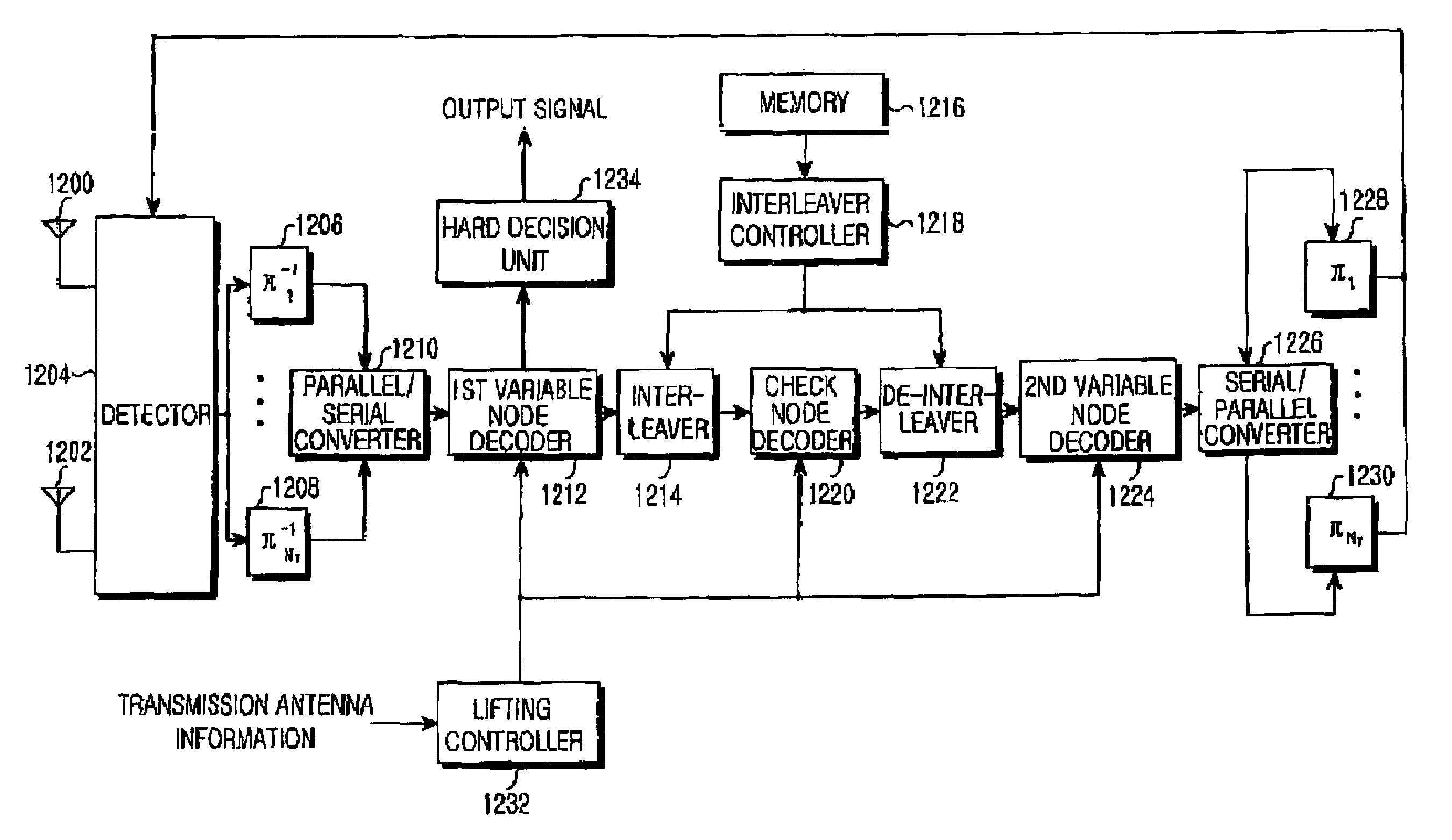
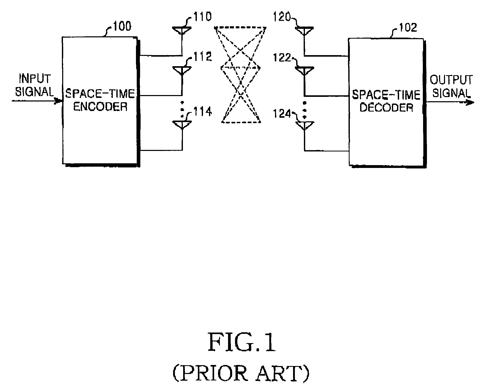
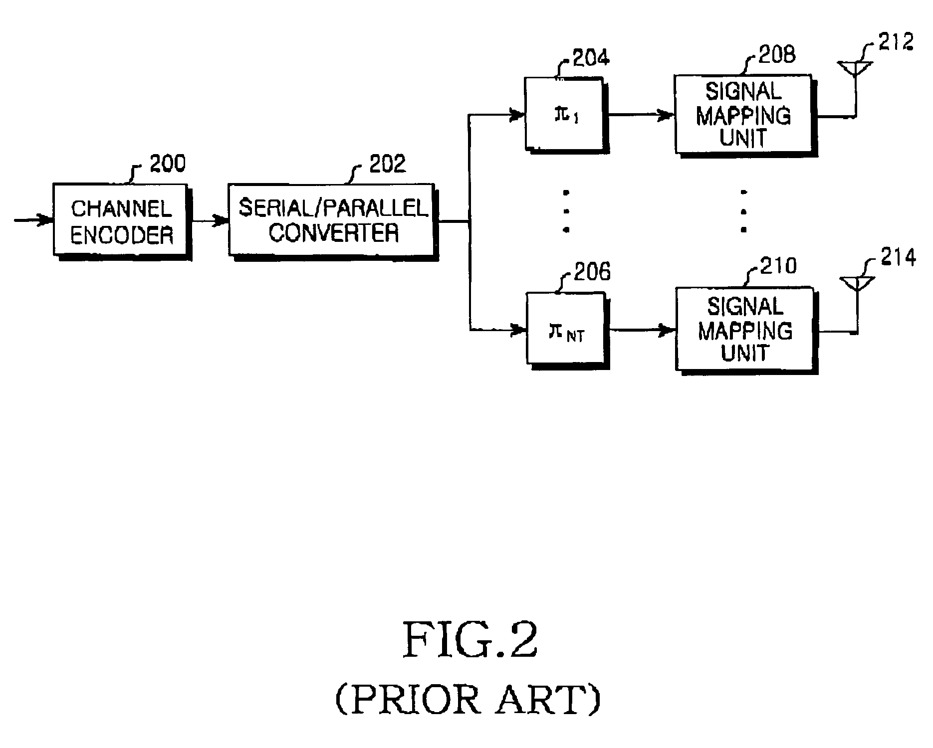
[0047]Accordingly, the present invention has been designed to solve the above and other problems occurring in the prior art, and it is an object of the present invention to provide a layered space-time coding / decoding apparatus and method utilizing a lifting low density parity check code for improving a correlation between bit arrays transmitted through a plurality of antennas in a wireless communication system using a plurality of antennas.
[0048]Another object of the present invention is to provide an apparatus and a method for transmitting data without an error by improving a relationship between bit arrays transmitted through a multiple antenna.
[0049]Still another object of the present invention is to provide an apparatus and a method for effectively transmitting bit arrays, if a number of antennas is larger than a number of bit arrays to be transmitted at a predetermined time.
[0050]Still another object of the present invention is to provide an apparatus and a method for expanding a layered space-time code and restoring data received through an LDPC coding scheme, thereby obtaining superior reliability.

Problems solved by technology

However, if the error occurs due to the channel environment, an iterative decoding is performed in order to precisely decode the reception signal.
According to Shannon's channel coding theory, if an optimal coding is performed with regard to information, there is a limitation to reduce an error occurring in a channel having noise without causing loss of an information transmission rate.
However, if the turbo codes are employed, the number of operations may increase, thereby causing complexity.
In addition, as the number of interleavers and iterative decoding operations increase, a time delay may occur, making a real time process difficult.
As a result, the LDPC code has not been implemented for a long time.
However, if a plurality of cycles having a short length exist in the factor graph of the LDPC code, performance of the LPDC code may be degraded.
Therefore, it is difficult to use various antennas.
That is, a channel encoder used for two antennas cannot be used for three antennas.
However, it is impossible to make high correlation between transmission signals if a random channel code is used.
That is, using the layered space-time code, the signals are individually transmitted to the antennas, and superior performance cannot be ensured.
However, if the LDPC code is randomly designed, it is difficult to improve correlation between signals transmitted to antennas.

Method used


Image

  • Method and apparatus for space-time coding using lifting low density parity check codes in a wireless communication system
  • Method and apparatus for space-time coding using lifting low density parity check codes in a wireless communication system
  • Method and apparatus for space-time coding using lifting low density parity check codes in a wireless communication system

Examples


embodiment 1

[0090]FIG. 7A illustrates a matrix in which an identity matrix is placed in a position of an element having a value of “1” in a 4×8 matrix 700, and a 0-matrix is placed in a position of an element having a value of “0”, thereby lifting a basic 4×8 matrix 702 into a 8×16 matrix 704. Referring to FIG. 7A, the parity check matrix (H) 700 is converted into the basic 4×8 matrix 702 and each element having a value of “1” in the parity check matrix is replaced with a 2×2 matrix through a predetermined method as described with reference to FIG. 6A. That is, 13 elements having a value of “1” in the 4×8 parity check matrix (H) 700 are replaced with the 2×2 sub-matrix including S1 to S13, thereby lifting the parity check matrix (H) 700.

[0091]The 2×2 sub-matrix of S1 to S13 can be embodied in various patterns. In FIG. 7A, S1 to S13 are represented in the form of an identity matrix. Therefore, the 4×8 parity check matrix (H) 700 is lifted into the 2×2 matrix and the 8×16 matrix 704 is created.

[0...

embodiment 2

[0094]Hereinafter, a second embodiment of the present invention for improving a correlation between bit arrays transmitted to each antenna will be described with reference to FIGS. 8A and 8B.

[0095]Generally, variable nodes connected to the same check node have a high correlation with each other during a decoding procedure. Therefore, in a layered space-time code using the lifting LDPC code according to the second embodiment of the present invention, data transmitted to different antennas are connected to the same check node, thereby improving correlation between data transmitted to a multiple antenna. For example, differently from the first embodiment illustrated in FIGS. 7A and 7B, the second embodiment illustrated in FIGS. 8A and 8B does not replace the elements having a value of “1” with the identity matrix, but replace the elements with a permutation matrix, thereby improving correlation between transmission signals.

[0096]In addition, as shown in Equation (1), two 2×2 permutatio...


PUM


Abstract

A mobile communication system and method for transmitting signals through a plurality of transmission antennas by space-time coding the signals. The signals are transmitted using a low density parity check code. A lifting low density parity check matrix is formed by expanding values of elements in a low density parity check matrix with a sub-matrix corresponding to a number of the transmission antennas. The signals to be transmitted are coded using the lifting low density parity check matrix. Thereafter, the coded signals are serial / parallel converted and transmitted through the transmission antennas.

Description

PRIORITY[0001]This application claims priority to an application entitled “Method and Apparatus For Space-Time Coding Using Lifting Low Density Parity Check Codes In A Wireless Communication System” filed with the Korean Intellectual Property Office on Oct. 13, 2003 and assigned Serial No. 2003-70997, the contents of which are incorporated herein by reference.BACKGROUND OF THE INVENTION[0002]1. Field of the Invention[0003]The present invention relates generally to an encoder / decoder of a wireless communication system using a plurality of antennas, and more particularly to a method and an apparatus for space-time coding / decoding using low density parity check codes.[0004]2. Description of the Related Art[0005]According to a space-time coding technique, signals output through a coding scheme are transmitted through a plurality of transmission antennas in such a manner that the coding scheme used in a time region can be also embodied in a spatial area, thereby achieving a low error rat...

Claims


Application Information

Patent Timeline
Patent Type & Authority Patents(United States)
IPC IPC(8): H04B7/02H04J99/00H04L1/00H04L1/06
CPCH04L1/0057H04L1/0656H04L1/0071H04B7/02
Inventor JEONG, HONG-SILKIM, JAE-YOELCHAE, CHAN-BYOUNG
Owner SAMSUNG ELECTRONICS CO LTD
Learn More