
Power control

a power control and power technology, applied in the field of power control, can solve the problems of small efficiency, interference with the reception of adjacent base stations, and low power efficiency of the whole system, and achieve the effects of increasing system efficiency, high maximum output power, and high efficiency

Inactive Publication Date: 2010-05-11
INTELLECTUAL VENTURES I LLC
View PDF13 Cites 12 Cited by
  • Summary
  • Abstract
  • Description
  • Claims
  • Application Information

AI Technical Summary

Benefits of technology

[0037]The invention provides a possibility to use higher maximum output power with higher efficiency than tolerated by conventional specifications. For example, it is possible to increase efficiency of systems that use multi-carrier signals like OFDM and that thereby have low power efficiency in the mobile transmitter in conventional systems.
[0038]By means of some embodiments of the invention it is possible to increase the maximum link distance in the area of low BTS density. That is, in the rural area the base station separation can be increased.

Problems solved by technology

Typically, the maximum available output power of mobile device has an effect on the base station density in the network and also on the network's operating expenses and capital expenses.
The reason for setting such restrictions is that ACP interferes with reception of the adjacent base stations if the ACP level is too high.
Especially in systems, which use signals with high PAPR (Peak-to-Average-Power Ratio), ACPR (Adjacent Channel Power Ratio) requirements of specifications restrict the maximum transmission power level of the mobile devices and PAs of the mobile devices have to continuously operate with high backoff and with very small efficiency in order to maintain sufficient linearity.
Because the ACPR requirements are derived on the basis of the worst-case scenario, the whole system is actually operating with low power efficiency and the idle and operation times or ranges of the system remain small.
Current specifications do not allow higher values of ACP than the value derived from the minimum attenuation to receivers operating on adjacent channels.

Method used


Image

  • Power control
  • Power control
  • Power control

Examples


Embodiment Construction

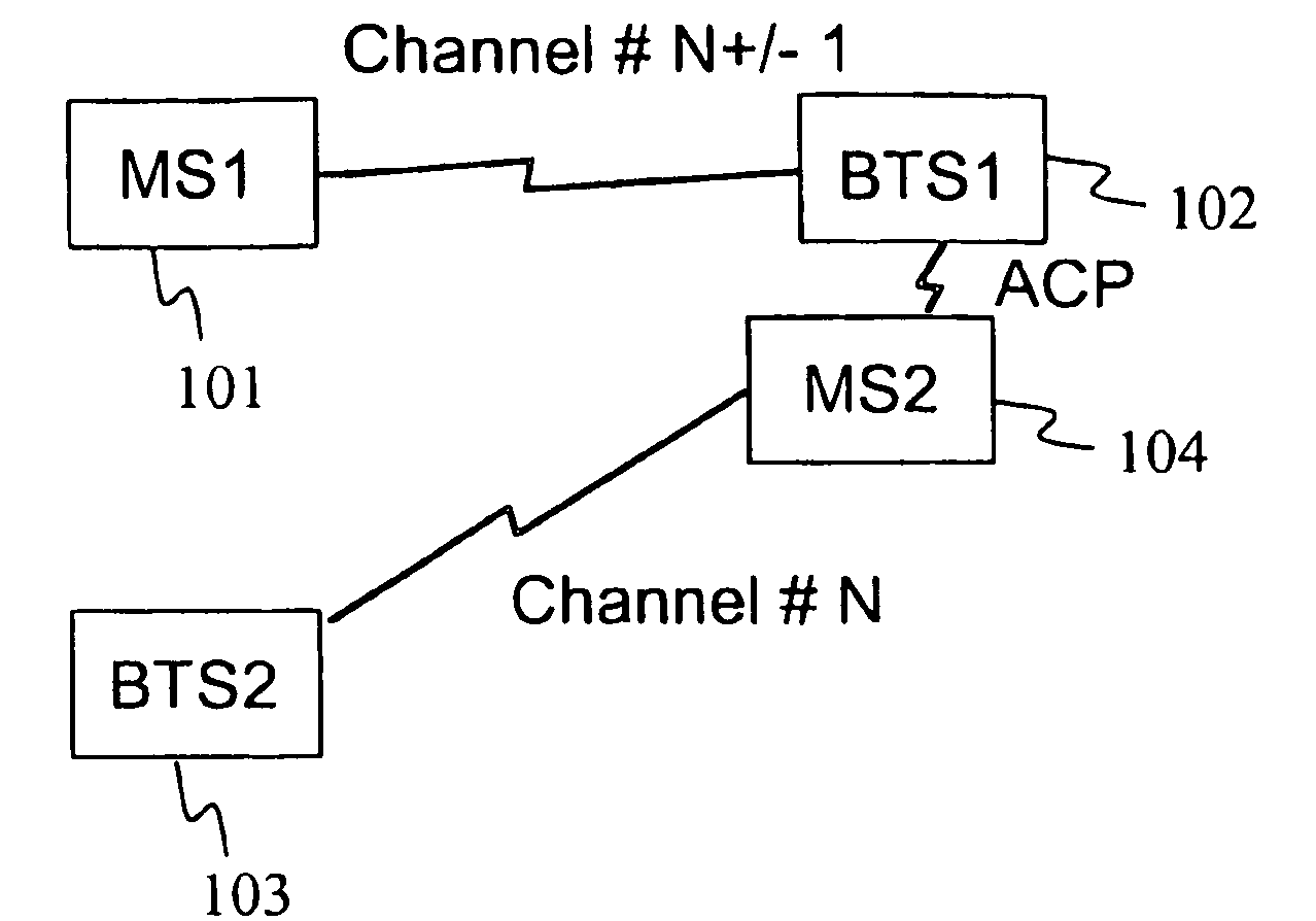
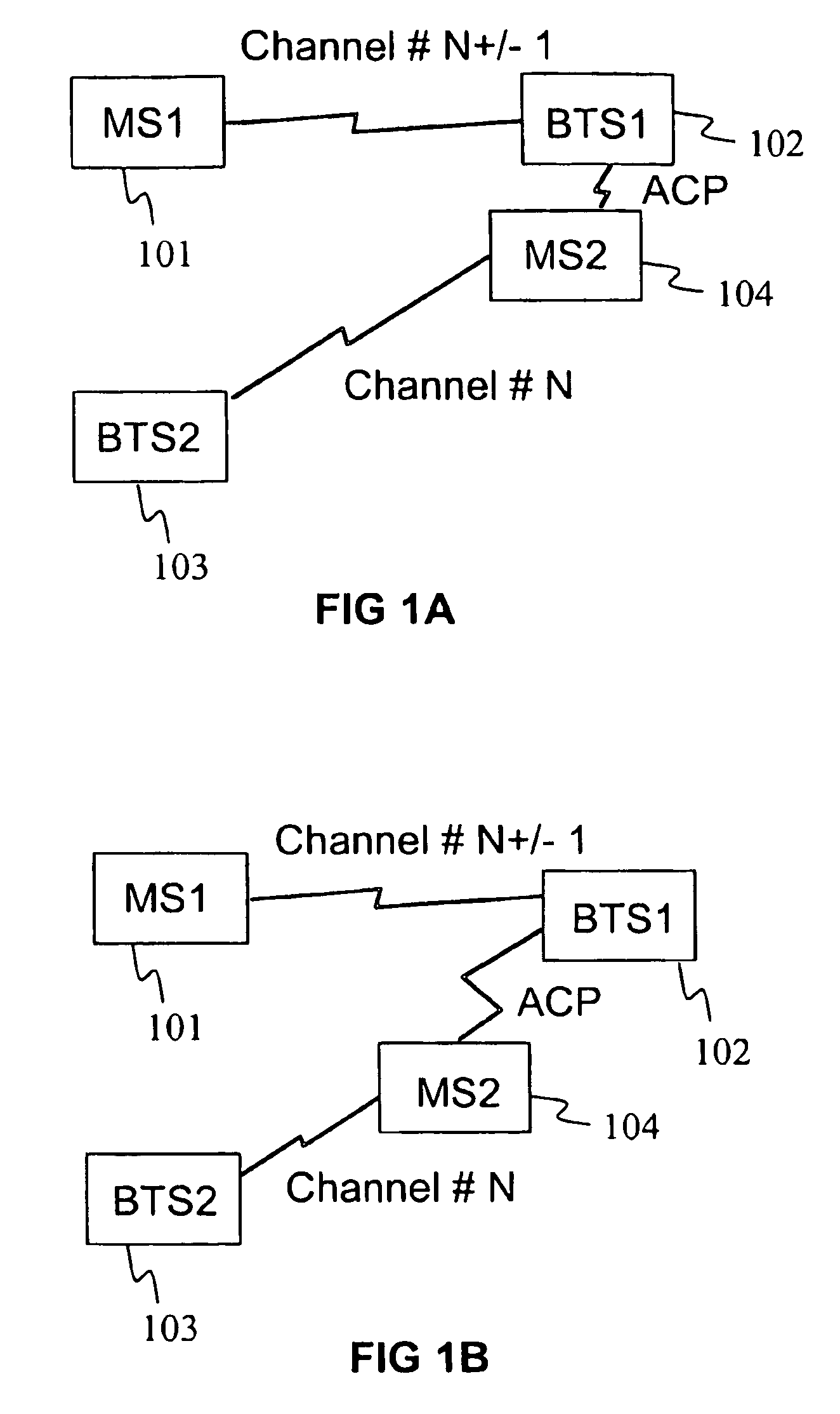
[0050]FIGS. 1A and 1B illustrate systems wherein the invention may be employed and a basic idea of the invention. Both Figures comprise a first mobile station (MS1) 101, a second mobile station (MS2) 104, a first base station (BTS1) 102 and a second base station (BTS2) 103. BTS1 and BTS2 operate on adjacent channels. MS2 transmits to BTS2 on channel number N and BTS2 receives signals on channel number N. Correspondingly, MS1 transmits to BTS1 on channel number N+1 (or N−1) and BTS1 receives signals on channel N+1 (or N−1).

[0051]In FIG. 1A, MS2 is in proximity of BTS1. The emission mask of the MS2 has to be such that BTS1 is able to receive signals from MS1 even when MS2 is this close to BTS2. That is, ACP of MS2 on channel N+1 (or N−1) may not be so high that it would interfere with the signals of MS1 at BTS1. In conventional power control algorithms this ACP requirement has to be met over the whole area of the system; that is, irrespective of the distance between MS2 and adjacent b...


PUM


Abstract

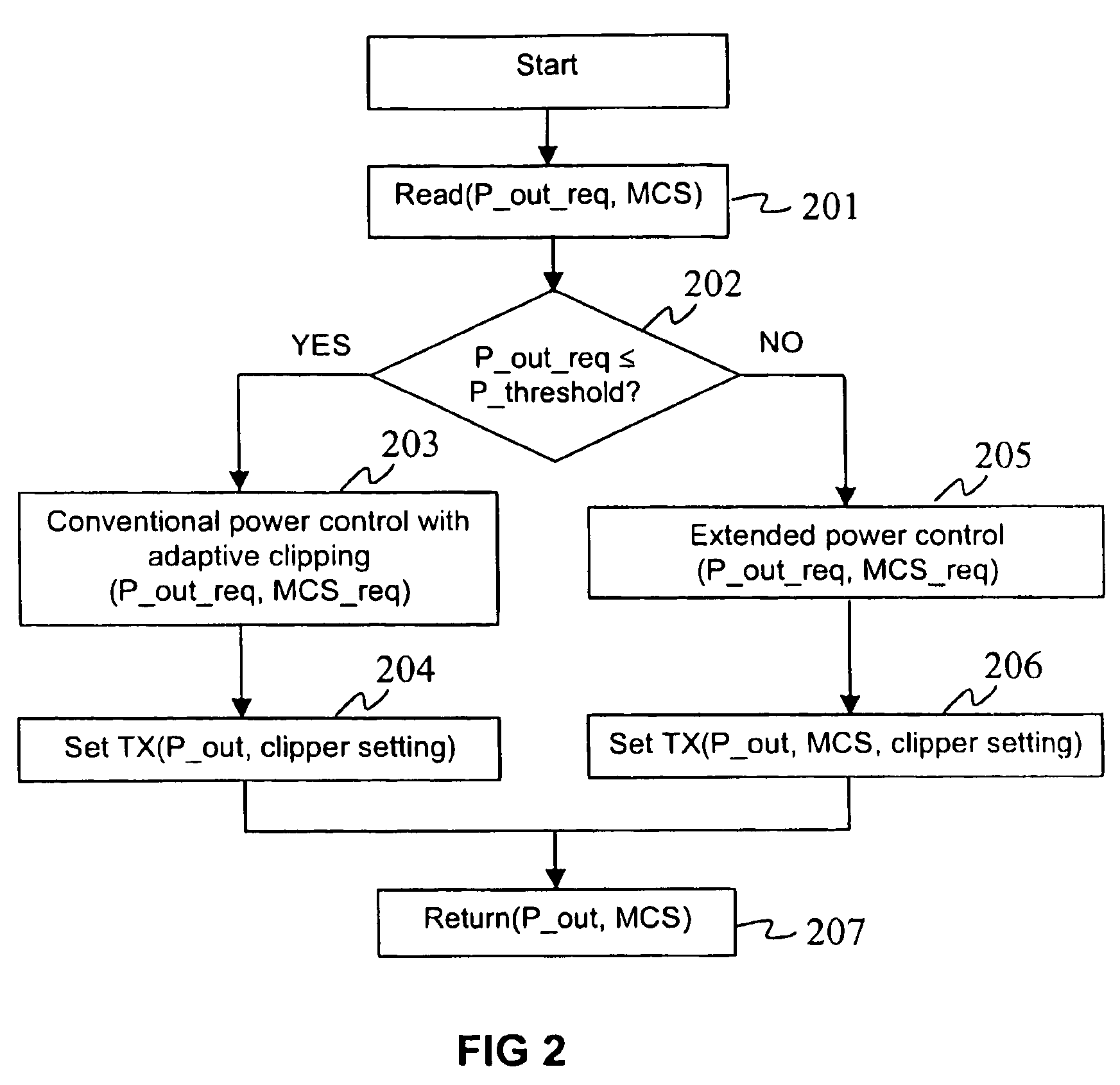
The invention relates to a method for controlling output power of a radio transmitter, the radio transmitter operating on a radio channel. The method includes determining requested output power level, and deriving output power, which is to be used, on the basis of a power control algorithm having at least a first and a second power control area, maximum output power of the first area being derived at least on the basis of theoretical minimum attenuation to adjacent receivers, and maximum output power of the second area being derived at least on the basis of actual minimum attenuation to adjacent receivers, wherein an adjacent receiver is a receiver operating on an adjacent channel with respect to the operating channel of said radio transmitter.

Description

FIELD OF THE INVENTION[0001]The invention relates to power control and especially to transmission power control between a mobile device and some other radio network equipment such as a base station.BACKGROUND OF THE INVENTION[0002]Maximum link range of a mobile device operating in a mobile communication network is strongly dependent on the maximum available output power of such device. Typically, the maximum available output power of mobile device has an effect on the base station density in the network and also on the network's operating expenses and capital expenses.[0003]The maximum output power of a mobile device is dependent on the maximum available DC power, signal waveforms, and minimum possible link distance to adjacent base stations operating on adjacent channels. The minimum distance to the base stations operating on adjacent channels is important because power amplifiers (PA) are non-linear elements and thereby generate so-called adjacent channel power (ACP). RF (Radio Fr...

Claims


Application Information

Patent Timeline
Patent Type & Authority Patents(United States)
IPC IPC(8): H04B7/00
CPCH04W52/243
Inventor SEPPINEN, PAULIKAUNISTO, RISTO
Owner INTELLECTUAL VENTURES I LLC
Learn More