
Joining mechanism for lightweight applications

a technology of joining mechanism and lightweight, applied in the direction of rod connection, coupling, instruments, etc., can solve the problems of insufficient holding of joined pieces firmly in place, prior art providing nothing satisfactory, etc., and achieve the effect of facilitating construction

Inactive Publication Date: 2010-05-11
ICHINO TED
View PDF8 Cites 5 Cited by
  • Summary
  • Abstract
  • Description
  • Claims
  • Application Information

AI Technical Summary

Benefits of technology

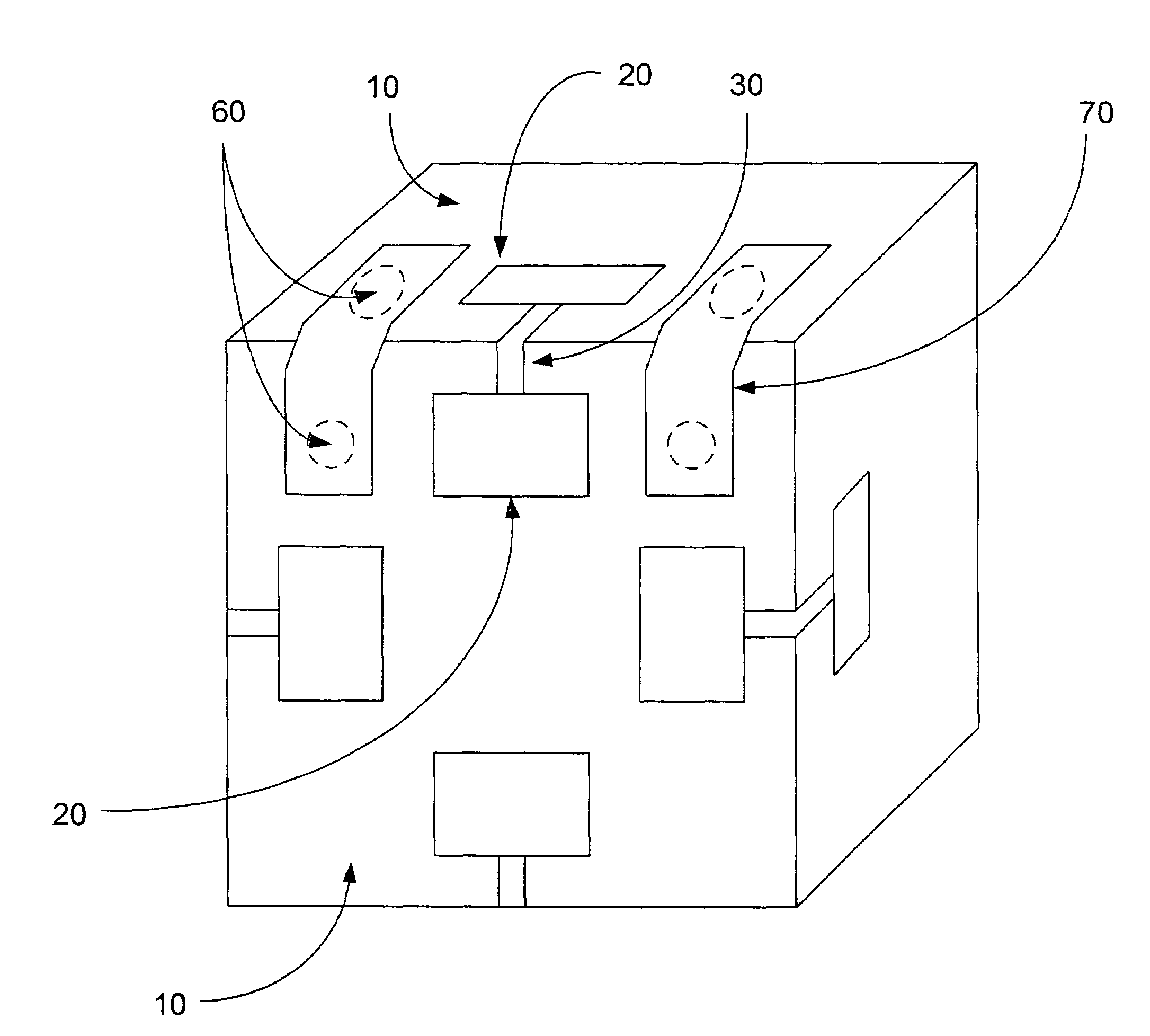
[0121]The present invention recognizes a new use for polycarbonate plastic as a joining mechanism, or tab. Polycarbonate plastic can easily be cut with regular scissors; it is rust-proof and resistant to corrosion. Polycarbonate plastic is lightweight and inexpensive, and a thin tab of polycarbonate plastic can be flexed through a wide range of motion without permanent deformation; the range of motion of a polycarbonate plastic tab far exceeds that of a metal strip of a corresponding size. Polycarbonate plastic can be bent and creased and will subsequently hold an angle and preferentially bend at the crease; this is especially useful for facilitating the construction of Platonic and Archimedean solids from component regular polygons.
[0122]Polycarbonate plastic strips, or tabs, by themselves, act more as connectors than fasteners, and often prove insufficient to hold the joined pieces firmly enough in place. However, they can readily be supplemented with Velcro hook and loop whereby the plastic tabs provide the initial fit and orientation of the pieces that are to be joined, and the Velcro hook and loop, once applied, provides support and stability to the joined pieces. Together, the connecting means provided by the polycarbonate plastic tabs coupled with the supporting means provided by the Velcro yield an effective and easy-to-use fastening means by which two or more polygons can be conveniently and securely joined.
[0124]The Platonic solids must satisfy the constraint that the same number of identical regular polygons must meet at each vertex. If this constraint is relaxed to allow non-identical polygons to meet at the vertices, the thirteen Archimedean solids become possible. The same joining mechanism that proved helpful in constructing the Platonic solids proves equally useful in the construction of Archimedean solids. The same regular polygons that were used to make Platonic solids can be recycled to make Archimedean solids, and the same joining mechanism employed. However, due to the large number of faces of Archimedean solids compared to Platonic solids, smaller polygons might be desirable, to restrict the final polyhedron to a manageable size.
[0127]The joining mechanism of the present invention will greatly facilitate the construction of all of these figures, providing that a slot capable of accepting a polycarbonate plastic tab is to be found in the center of each polygon face that is to be joined. Not every side of every polygon needs a plastic connector, however. As a polyhedron begins to take shape, the angles at which its polygons must meet become more apparent, often dispensing with the need for a tab; the polygons can then be Velcroed directly into place once one or more edges have been properly aligned.

Problems solved by technology

Polycarbonate plastic strips, or tabs, by themselves, act more as connectors than fasteners, and often prove insufficient to hold the joined pieces firmly enough in place.
A joining mechanism that can accommodate the wide range of angles described by the faces of the various Platonic solids (acute for the tetrahedron; normal for the hexahedron; and obtuse for the dodecahedron and icosahedron) was sought, but the Prior Art provided nothing that was satisfactory.

Method used


Image

  • Joining mechanism for lightweight applications
  • Joining mechanism for lightweight applications
  • Joining mechanism for lightweight applications

Examples


Embodiment Construction

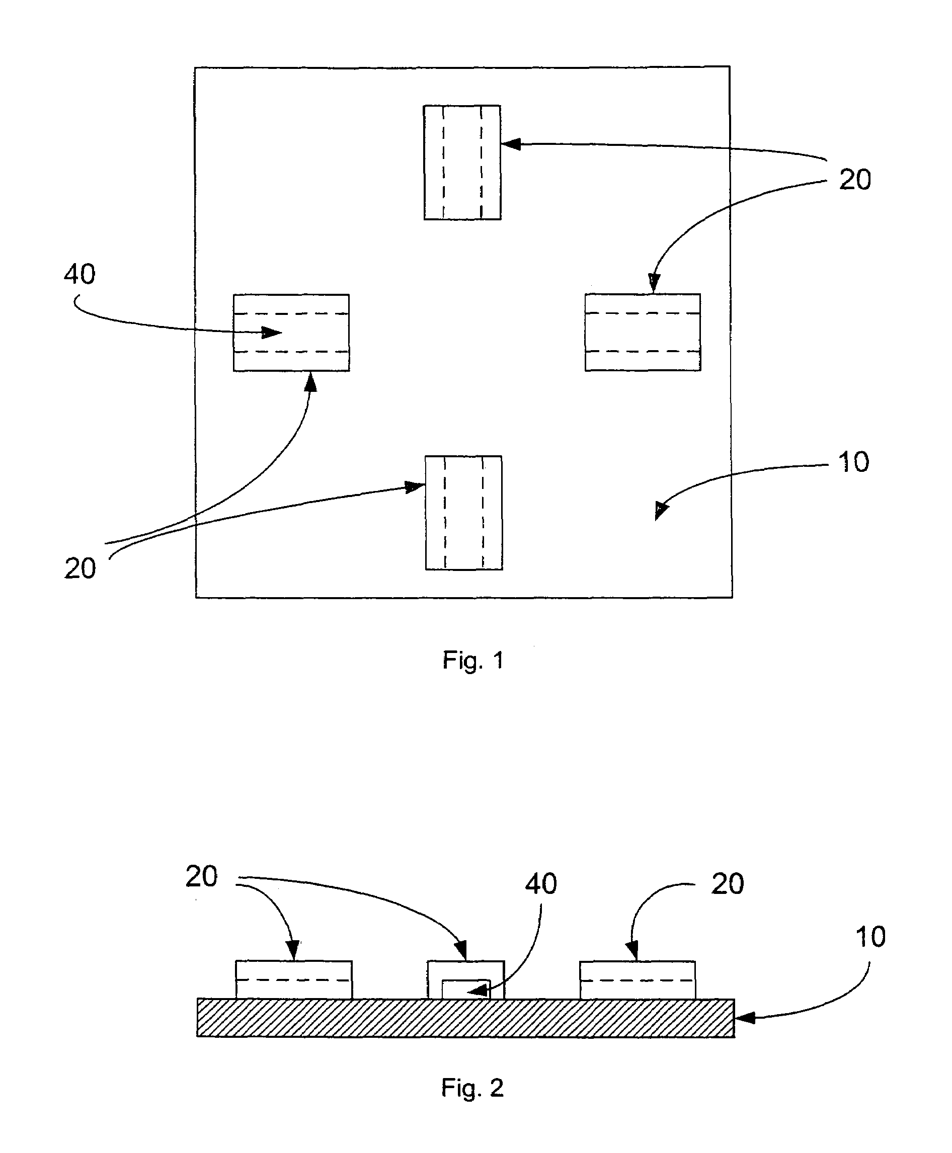
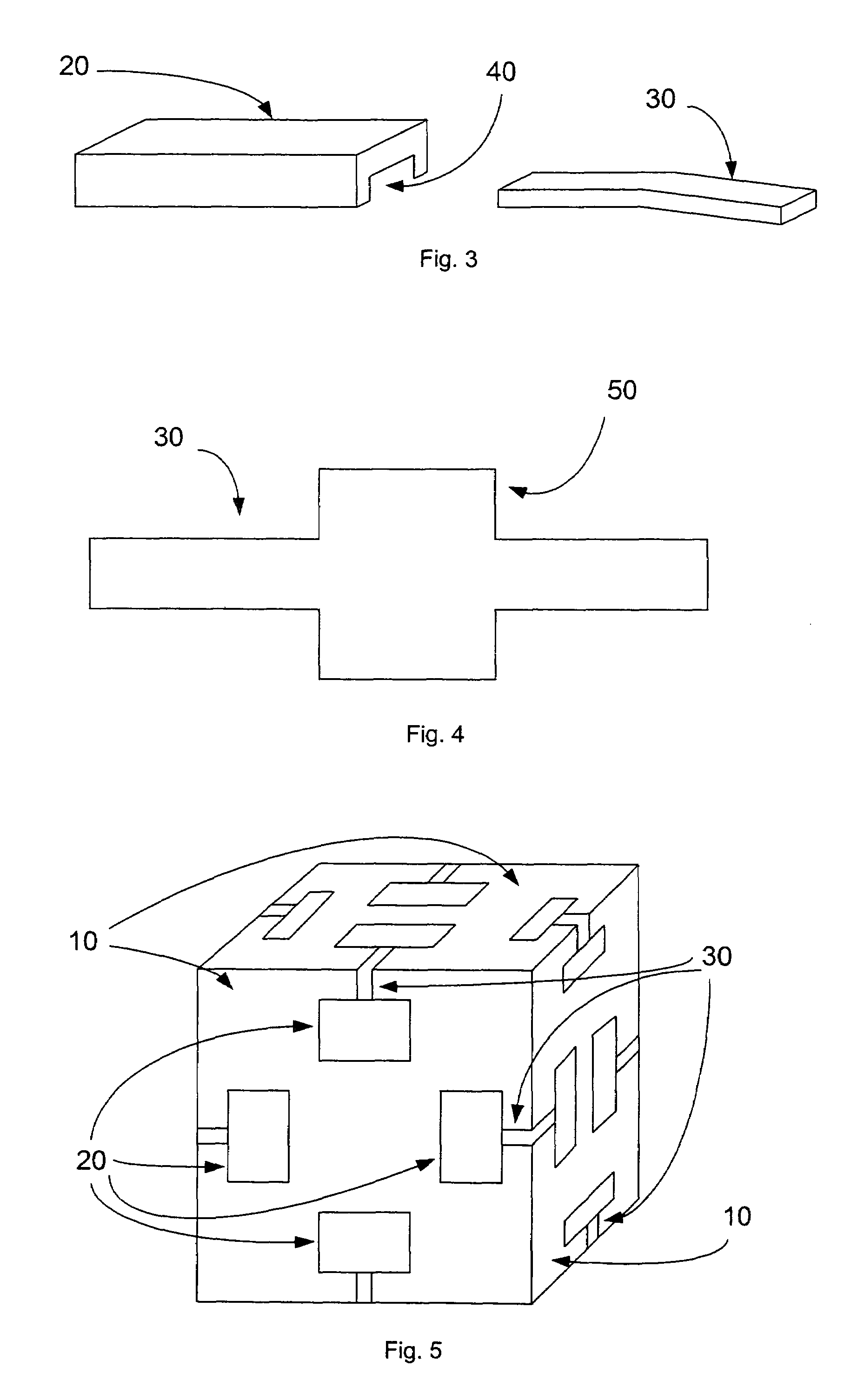
[0142]FIG. 1 is a top view of a regular polygon equipped with a joining mechanism at the center of each side. Although for simplicity a square has been depicted, any regular polygonal-shaped planar polygonal member (in particular, triangles, squares, pentagons, hexagons, octagons, and decagons) can serve as Object 10. Indeed, Object 10 need not be a regular polygon at all. Any shape that is to be joined to another shape can comprise Object 10. U-shaped channel member 20 exists solely to form a slot by bounding Channel 40 by Object 10. The slot thus formed is intended to accept resilient joining Tab 30 (pictured in FIG. 3). To create slots for Tabs 30, U-shaped channels 20 are installed perpendicular to one or more sides of regular polygons that will be building blocks for Platonic and Archimedean polyhedra. U-shaped channels 20 are additionally located at the midpoint of a side and slightly inset from the edge in order to accommodate a pre-formed angle in Tab 30. Note that U-shaped ...


PUM


Abstract

A convex polyhedron is formed from planar polygonal members, wherein aligned sides of adjacent abutting polygonal members meet to form edges of the polyhedron. A flexible polycarbonate plastic joining tab fits into slots in the centers of sides of adjacent polygonal members to enable adjustment of the dihedral angle between the adjacent polygonal members. A supplemental source of support such as hook and loop strips are used to fasten joined polygonal members securely in place at a desired alignment and dihedral angle. The polygonal members have mirrored interior faces which impart infinite internal reflections within an interior of the polyhedron, wherein one of the polygonal members is a two-way transparent mirror serving as a viewport, allowing a user to see into the infinitely-reflective interior of the polyhedron.

Description

CROSS-REFERENCE TO RELATED APPLICATIONS[0001]This application claims the benefit of provisional patent application Ser. No. 60 / 897,071 filed 23 Jan. 2007 by the present inventor.SEQUENCE LISTING[0002]None.BACKGROUND OF THE INVENTION[0003]1. Field of the Invention[0004]This invention pertains to joining and fastening mechanisms, especially for lightweight applications such as toys. The present invention resulted from a need to conveniently and securely attach polygons to each other in order to construct convex uniform polyhedra, the five regular polyhedra (Platonic solids) and the thirteen semi-regular polyhedra (Archimedean solids) being of particular interest.[0005]Nomenclature:[0006]The following descriptions and nomenclature have been excerpted from Polyhedron Models by Magnus J. Wenninger (pp. 1-3):[0007]“[A] plane figure may be defined as a set of line segments enclosing a portion of two-dimensional space. Such a plane figure is called a polygon. A polyhedron is then defined as...

Claims


Application Information

Patent Timeline
Patent Type & Authority Patents(United States)
IPC IPC(8): G09B23/04
CPCG09B23/04Y10T403/347Y10T403/342
Inventor ICHINO, TED
Owner ICHINO TED
Learn More