
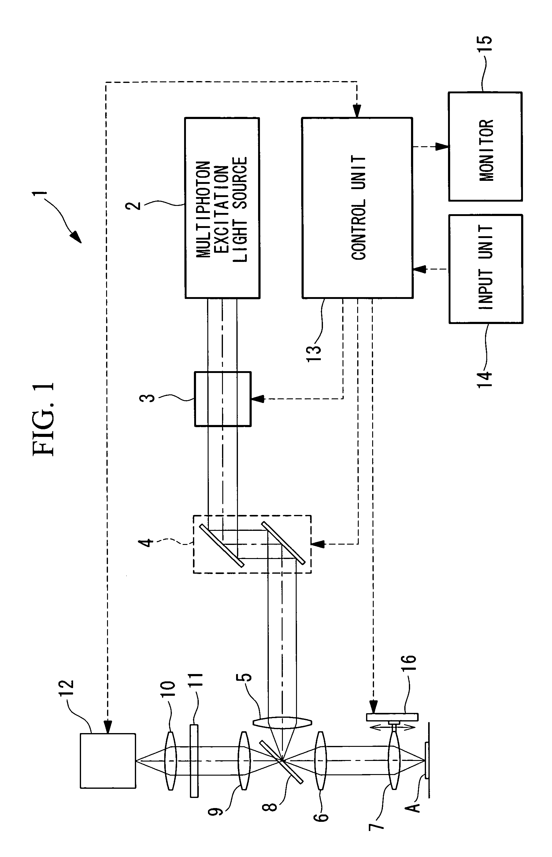
Scanning optical device which sets hardware in association with a depth of a focus position based on hardware set values stored in association with depths of focus positions

a technology of optical devices and depths, applied in the direction of optical radiation measurement, luminescent dosimeters, instruments, etc., can solve the problems of reducing the brightness information contained in image data itself, unable to construct fluorescence images, and unable to obtain clear fluorescence images. achieve the effect of easy to obtain a clear fluorescence imag

Active Publication Date: 2010-05-04
EVIDENT CORP
View PDF4 Cites 7 Cited by
  • Summary
  • Abstract
  • Description
  • Claims
  • Application Information

AI Technical Summary

Benefits of technology

[0011]The present invention provides a scanning optical device and an observation method that can easily obtain a clear fluorescence image irrespective of variation of scattering due to variation in depth of the focus position in a specimen.

Problems solved by technology

Fluorescence emitted from the inside of the specimen is scattered by the specimen, and thus there is a problem that a fluorescence image based on fluorescence generated at a deep position of the specimen is darker than a fluorescence image based on fluorescence generated at a shallow position of the specimen.
However, when the correction is made by subjecting obtained image data to the image processing, it induces a problem that the amount of brightness information contained in the image data itself is reduced and thus the corrected fluorescence image is unclear.
Therefore, even when the brightness is corrected by the image processing, no clear image can be constructed.

Method used


Image

  • Scanning optical device which sets hardware in association with a depth of a focus position based on hardware set values stored in association with depths of focus positions
  • Scanning optical device which sets hardware in association with a depth of a focus position based on hardware set values stored in association with depths of focus positions
  • Scanning optical device which sets hardware in association with a depth of a focus position based on hardware set values stored in association with depths of focus positions

Examples


second embodiment

[0062]Next, a scanning optical device according to the present invention will be described hereunder with reference to FIGS. 7 and 8.

first embodiment

[0063]In the following description of this embodiment, constituent elements of this embodiment which are common to the construction of the scanning optical device 1 described above are represented by the same reference numerals, and the description thereof is omitted.

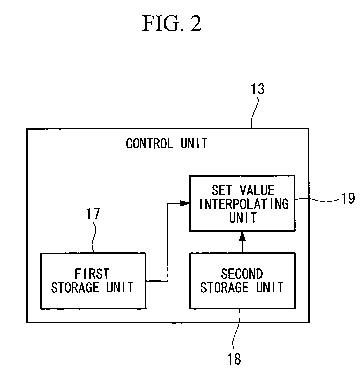
[0064]As shown in FIG. 8, the scanning optical device 1 according to this embodiment is different from the scanning optical device 1 according to the first embodiment in that the data to be stored in the second storage unit 18 are the absolute heights Z11 to Z15 of the respective focus positions in place of the distances d1 to d5 from the surface positions of the plurality of focus positions which are arranged in the depth direction of the specimen A at the observation position so as to be spaced from one another, in that the control unit 13 is provided with a third storage unit 20 for storing the absolute height Z20 at a new surface position, and in the operation of the set value interpolating unit 19.

[0065]The set va...

third embodiment

[0067]A scanning optical device according to the present invention will be described with reference to FIGS. 9 and 10.

[0068]In the following description of this embodiment, constituent elements common to the construction of the scanning optical device 1 according to the first embodiment described above are represented by the same reference numerals, and the description thereof is omitted.

[0069]The scanning optical device according to this embodiment is different from the scanning optical device 1 according to the first embodiment in that the information stored in the first storage unit 17 contains not only the absolute height Z10 of the surface position, but also the hardware set value HW01 at the surface position, in that the control unit 13 is provided with a third storage unit 20 for storing the absolute height Z20 of a new surface position and a hardware set value HW02, and in the operation of the set value interpolating unit 19.

[0070]The set value interpolating unit 19 calculat...


PUM


Abstract

A clear fluorescence image is easily obtained irrespective of variation of scattering due to variation of the depth of a focus position in a specimen. A scanning optical device includes a laser light source for emitting laser light, a scanning unit for scanning the laser light emitted from the laser light source on the specimen, a focus depth adjusting unit for adjusting the depth of the focus position in the specimen of the laser light to be scanned, a fluorescence detector for detecting fluorescence generated from the focus position of the laser light in the specimen, a reference depth information storage unit for storing the absolute height of a predetermined reference depth of the focus position of the laser light in the specimen by the focus depth adjusting unit, and a hardware setting storage unit for storing the relative height to the absolute height of the reference depth at each focus position of the laser light and at least one set value of the laser light source, the scanning unit, and the fluorescence detector in association with each other.

Description

BACKGROUND OF THE INVENTION[0001]1. Field of the Invention[0002]The present invention relates to a scanning optical device and an observation method.[0003]This application is based on Japanese Patent Application No. 2007-105568, the content of which is incorporated herein by reference.[0004]2. Description of Related Art[0005]There has been hitherto known a scanning optical device for obtaining a bright fluorescence image having high resolution in the depth direction of a specimen by using a multiphoton excitation phenomenon. Fluorescence emitted from the inside of the specimen is scattered by the specimen, and thus there is a problem that a fluorescence image based on fluorescence generated at a deep position of the specimen is darker than a fluorescence image based on fluorescence generated at a shallow position of the specimen.[0006]In order to solve this problem, for example, according to the invention disclosed in Japanese Unexamined Patent Application, Publication No. 2000-2755...

Claims


Application Information

Patent Timeline
Patent Type & Authority Patents(United States)
IPC IPC(8): G02B7/04G02B27/40G02B27/64
CPCG01N21/6456G02B2207/113
Inventor YAMASHITA, YUSUKEOKADA, JUNICHIUENO, MAKIO
Owner EVIDENT CORP
Learn More