
Apparatus and method for delivering water vapor to a gas

a technology of apparatus and water vapor, applied in the direction of heating types, combustion types, separation processes, etc., can solve the problems of respiratory irritation and discomfort of patients

Inactive Publication Date: 2010-05-04
BRIDGE BANK NAT ASSOC
View PDF118 Cites 26 Cited by
  • Summary
  • Abstract
  • Description
  • Claims
  • Application Information

AI Technical Summary

Problems solved by technology

It has been recognized that the delivery of oxygen and oxygen-enriched air to the respiratory tract of a patient often results in discomfort to the patient, especially when the air is delivered over an extended period of time.
It has also been recognized that the delivery of air having relatively low absolute humidity can result in respiratory irritation.

Method used


Image

  • Apparatus and method for delivering water vapor to a gas
  • Apparatus and method for delivering water vapor to a gas
  • Apparatus and method for delivering water vapor to a gas

Examples


Embodiment Construction

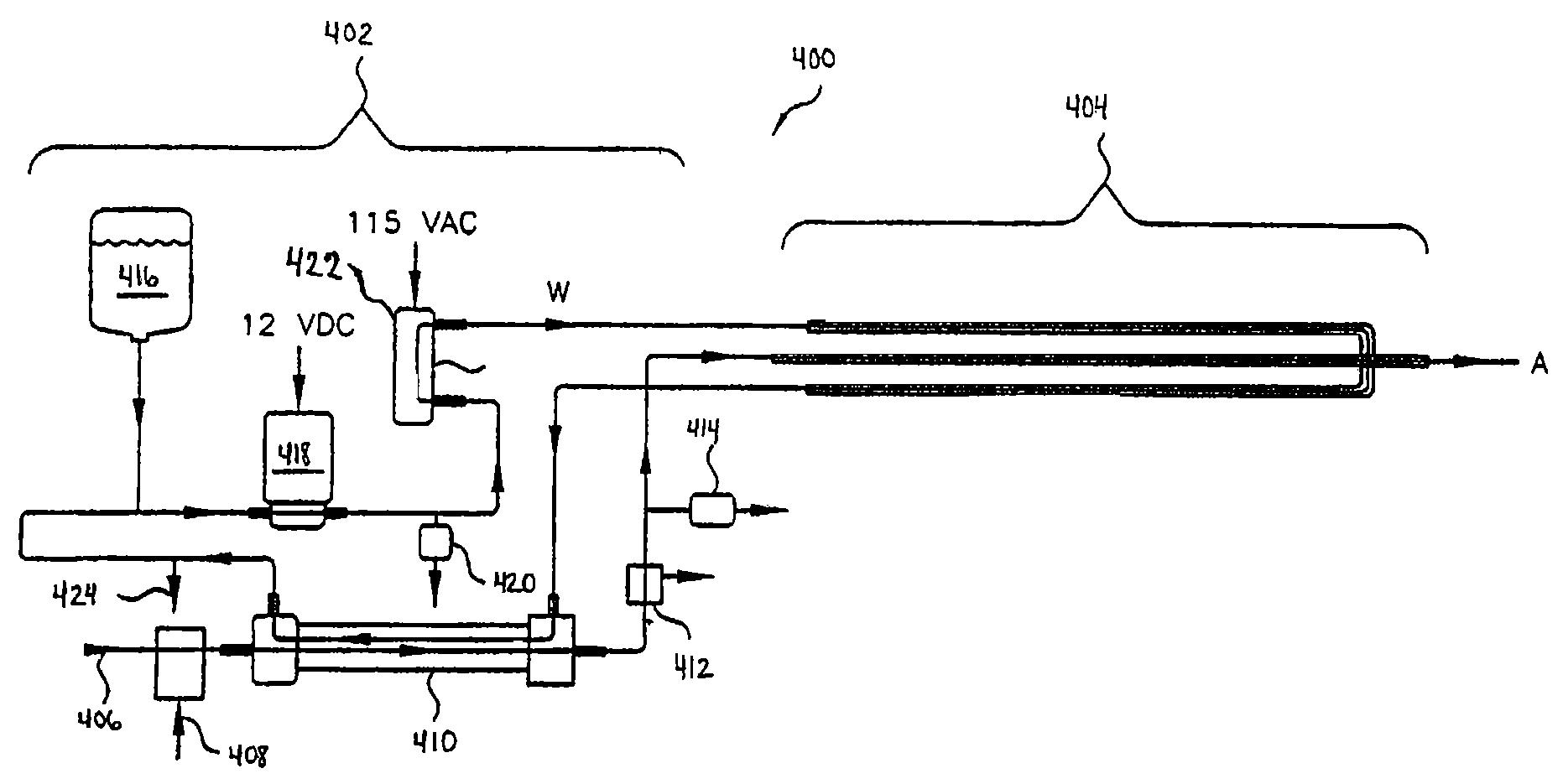
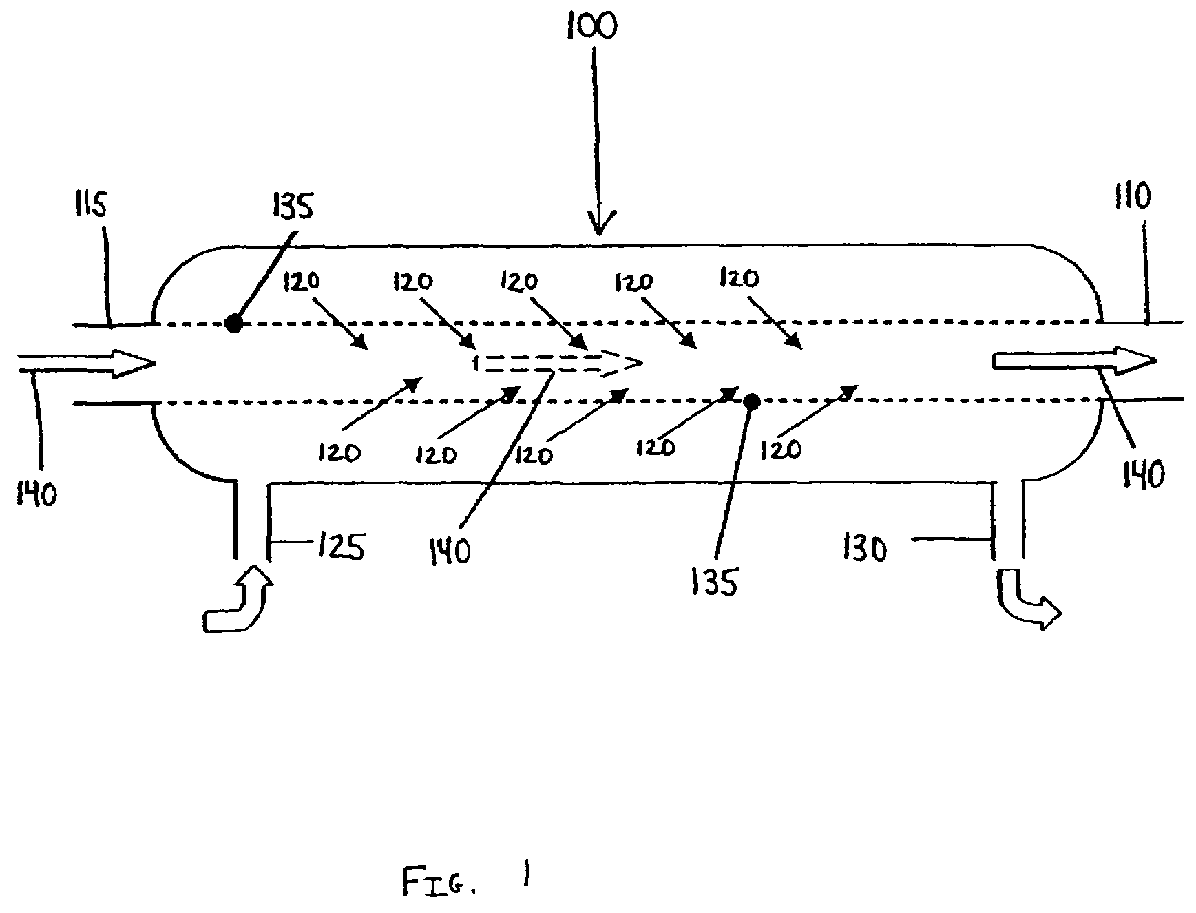
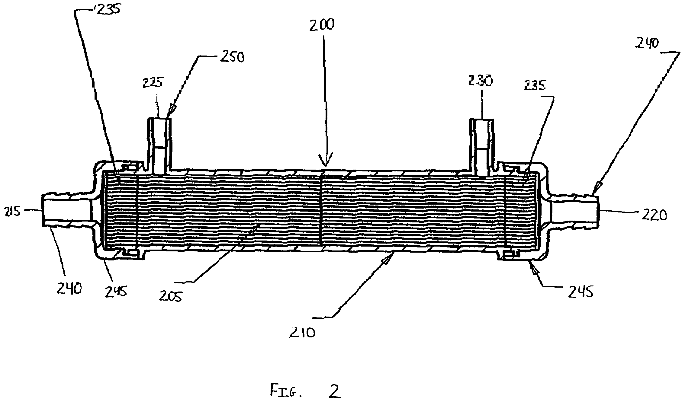
[0014]In the detailed description which follows, the features of the present invention will be described in connection with the delivery of humidified gas to a patient. FIG. 3 provides a schematic illustration of embodiments of system, in their entirety. FIGS. 1 and 2 illustrate embodiments of vapor flow cartridges that can be used in systems such as the system illustrated in FIG. 3.

[0015]Referring generally to the figures, an apparatus 100, 200 is provided for delivering water vapor to a gas. The apparatus 100, 200 includes a plurality of hollow fiber membranes 135, 205 each defining a passage for the flow of gas from an upstream end of said each passage to a downstream end of said each passage. An enclosure 210 encloses the hollow fiber membranes 135, 205 and has an air inlet 115, 215 positioned to direct air to the upstream end of each of the passages of the hollow fiber membranes 135, 205. An air outlet 110, 220 is positioned to direct air from the downstream end of each of the ...


PUM

PropertyMeasurementUnit
Flow rateaaaaaaaaaa

Abstract

An apparatus for delivering water vapor to a gas is formed from a plurality of hollow fiber membranes each defining a passage for the flow of gas from an upstream end of the passage and enclosed by an enclosure. The hollow fiber membranes have a combined surface area in the range of about 90 square centimeters to about 110 square centimeters. The enclosure contains an air inlet positioned to direct air to the upstream end of each of the passages of the hollow fiber membranes and an air outlet positioned to direct air from the downstream end of each of the passages of the hollow fiber membranes. The enclosure preferably has a water inlet positioned to direct water toward the outer surfaces of the hollow fiber membranes and a water outlet positioned to direct water from the enclosure.

Description

[0001]This application is a Continuation-In-Part of application Ser. No. 10 / 149,356, filed Jan. 29, 2003, now U.S. Pat. No. 7,341,046 which is a National Phase of PCT / US00 / 33346 filed Dec. 8, 2000.FIELD OF THE INVENTION[0002]The present invention relates to an apparatus and method for delivering water vapor to a gas. More particularly, this invention relates to a low flow vapor transfer cartridge that optionally allows water to pass into a gas stream at gas flow rates ranging from about 1 liter per minute to about 8 liters per minute without a transfer of water in a liquid state. The low flow cartridge acts as a complete or partial barrier against bacteria while simultaneously allowing the passage of water vapor.BACKGROUND OF THE INVENTION[0003]It has been recognized that the delivery of oxygen and oxygen-enriched air to the respiratory tract of a patient often results in discomfort to the patient, especially when the air is delivered over an extended period of time. It has also bee...

Claims


Application Information

Patent Timeline
IPC IPC(8): A61M16/00A61M15/00A61M16/06A61M16/10A61M16/14A61M16/16B01F23/10
CPCA61M16/16B01F3/022A61M16/145A61M16/109B01F5/0476A61M16/162B01F23/12B01F25/31421A61M16/10A61M16/06B01F23/20
Inventor NILAND, WILLIAM F.BAMFORD, OWEN S.CORTEZ, JR., FELINO V.
Owner BRIDGE BANK NAT ASSOC
Learn More