
Lamp, optical module, vehicle headlight including the same, and method for controlling color tone of emitted light

a technology of optical modules and headlights, applied in fixed installations, lighting and heating apparatus, lighting support devices, etc., can solve problems such as difficult color recognition, difficulty in traveling light from the headlights, and dark and monochrome whole field of vision

Active Publication Date: 2010-04-27
STANLEY ELECTRIC CO LTD
View PDF7 Cites 33 Cited by
  • Summary
  • Abstract
  • Description
  • Claims
  • Application Information

AI Technical Summary

Benefits of technology

The patent text describes a vehicle lighting device that can improve visibility in various driving conditions, such as rain, fog, and snow. The device includes a light source portion with two different colored light sources, a wavelength conversion layer, and a driving control unit. The driving control unit can control the two light sources independently, allowing for different color tones to be emitted from each optical module. The vehicle headlights can also include a vehicle environment information acquisition unit to control the light sources based on information related to the vehicle's operation and driving conditions. The technical effect of this patent is to provide a vehicle lighting device that can improve visibility in various driving conditions and driving modes.

Problems solved by technology

In addition, recognition of color can be difficult and therefore a whole field of vision can become dark and monochrome.
Therefore, the light from the headlight has difficulty in traveling forward to a distant location, and the scattered light can dazzle an oncoming driver.
Therefore, it is difficult for a driver to fully recognize the three dimensions of an object ahead of a vehicle.
In this case, however, the fog light is a separate lighting device from the headlight and has to be additionally installed or originally provided in a vehicle, thus increasing a burden to a manufacturer or user of the vehicle.

Method used


Image

  • Lamp, optical module, vehicle headlight including the same, and method for controlling color tone of emitted light
  • Lamp, optical module, vehicle headlight including the same, and method for controlling color tone of emitted light
  • Lamp, optical module, vehicle headlight including the same, and method for controlling color tone of emitted light

Examples


Embodiment Construction

[0053]In the configurations described above, the wavelength conversion material can perform wavelength conversion on the color of the light emitted from the first light source. Thereby, the lamp can emit both the first light of the original color and the wavelength converted light to the outside. Therefore, if the first light source is a blue LED chip for emitting blue light and the wavelength conversion material is a fluorescent material for wavelength converting light to yellow light, the yellow light is mixed with the blue light from the blue LED chip, so that white light (the resultant mixed light) is emitted to the outside.

[0054]Moreover, light from the second light source can be added to the white light (i.e., the mixed light that includes the blue light from the blue LED chip and the yellow light from the fluorescent material). Thus, the color of the light from the second light source is added to the white light.

[0055]Due to this, by changing the output of each of the light s...


PUM


Abstract

A lamp, an optical module, a vehicle headlight, and a method for controlling a color tone of the same can be configured to ensure visibility of the surroundings of a vehicle on a wet road in rainy weather, in dense fog, and on a snowpacked road, for example. The lamp can include a first LED chip which emits blue light, a second LED chip which emits light with a different color from blue. A wavelength conversion layer can be provided in front of light emitting areas of the first and second LED chips in an emitting direction, and can include a wavelength conversion material. A driving control unit can be configured to drive and control the first and second LED chips. The optical module can be configured to include the lamp along with optical components, such as a reflector. A vehicle headlight can include a plurality of optical modules. The control unit can be configured to control the ratio of light from the first and second LED chips, thereby obtaining light of a desired color.

Description

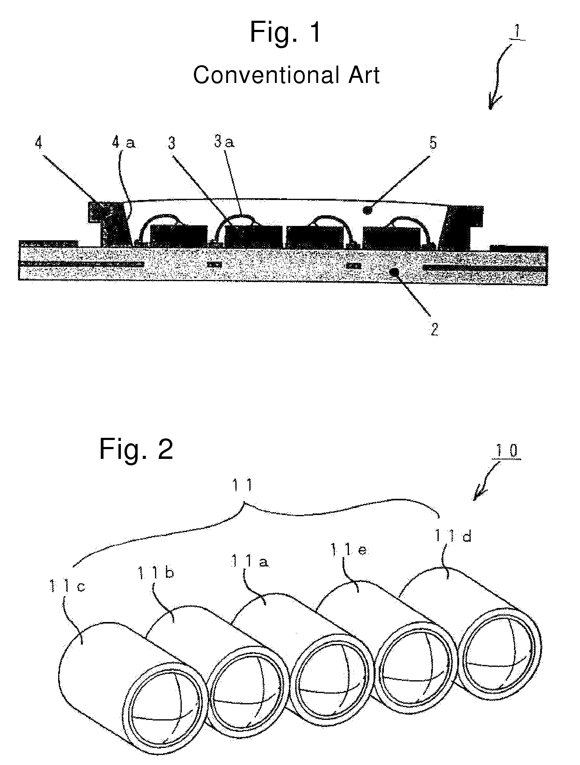
[0001]This application claims the priority benefit under 35 U.S.C. §119 of Japanese Patent Application No. 2005-176387 filed on Jun. 16, 2005, which is hereby incorporated in its entirety by reference.1. TECHNICAL FIELD[0002]The presently disclosed subject matter relates to a lamp for a vehicular lighting device used as a headlight or an auxiliary headlight provided in a front part of a vehicle, for example, and also relates to an optical module and a vehicle headlight including the same. Also, the disclosed subject matter relates to a method for controlling color tone of emitted light from a lamp.2. DESCRIPTION OF THE RELATED ART[0003]A conventional LED light source for use in a vehicle lighting device has a structure shown in FIG. 1, for example.[0004]The LED light source 1 includes: a base 2; at least one LED chip 3 (four LED chips are shown in this illustrated example) placed on the base 2; a reflector 4 provided on the base 2 to surround the LED chip 3, the reflector having a h...

Claims


Application Information

Patent Timeline
Patent Type & Authority Patents(United States)
IPC IPC(8): F21S8/10
CPCF21S48/1159F21S48/1388H05B33/0857B60Q2300/054B60Q2300/312H01L2924/3025Y10S362/80H01L2224/48091F21Y2101/02H01L25/0753H01L33/60H01L2924/00F21Y2115/10F21S41/125F21S41/155F21S41/255F21S41/321F21S41/43F21S41/365H05B45/20H05B45/00F21S41/148F21S41/176H01L2924/00014
Inventor YATSUDA, YASUSHIKOJIMA, SHINICHIKOIKE, TERUOKITA, YASUSHI
Owner STANLEY ELECTRIC CO LTD
Learn More