Bi-directional DC-DC converter and control method
a dc-dc converter and bi-directional technology, applied in the direction of process and machine control, battery/fuel cell control arrangement, instruments, etc., can solve the problems of inability to obtain the desired bi-directional voltage ratio easily, too low voltage during a step-down operation, and inability to meet the step-up ratio, etc., to achieve the effect of expanding the step-up ratio, and expanding the duty ratio rang
- Summary
- Abstract
- Description
- Claims
- Application Information
AI Technical Summary
Benefits of technology
Problems solved by technology
Method used
Image
Examples
first embodiment
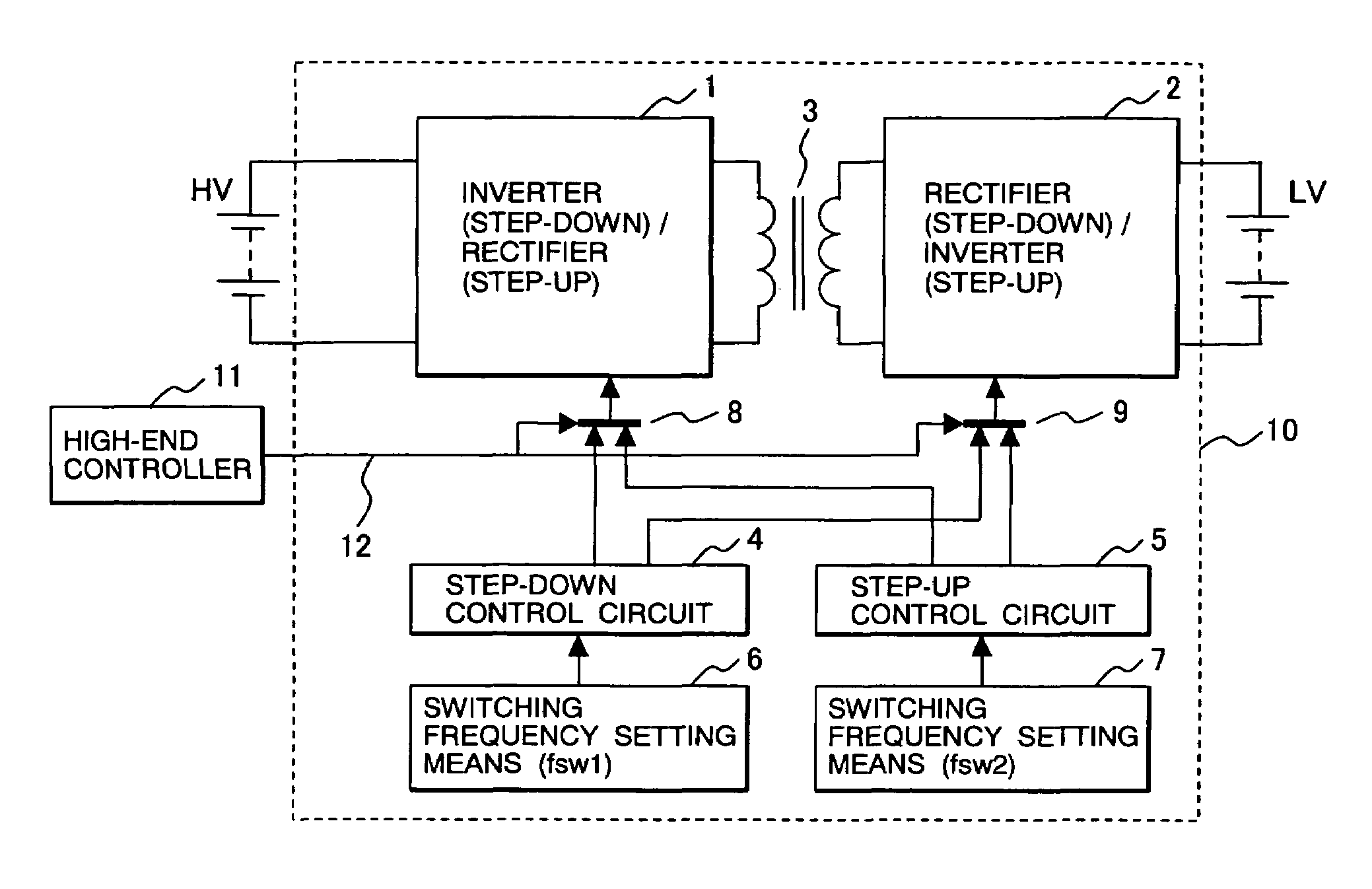
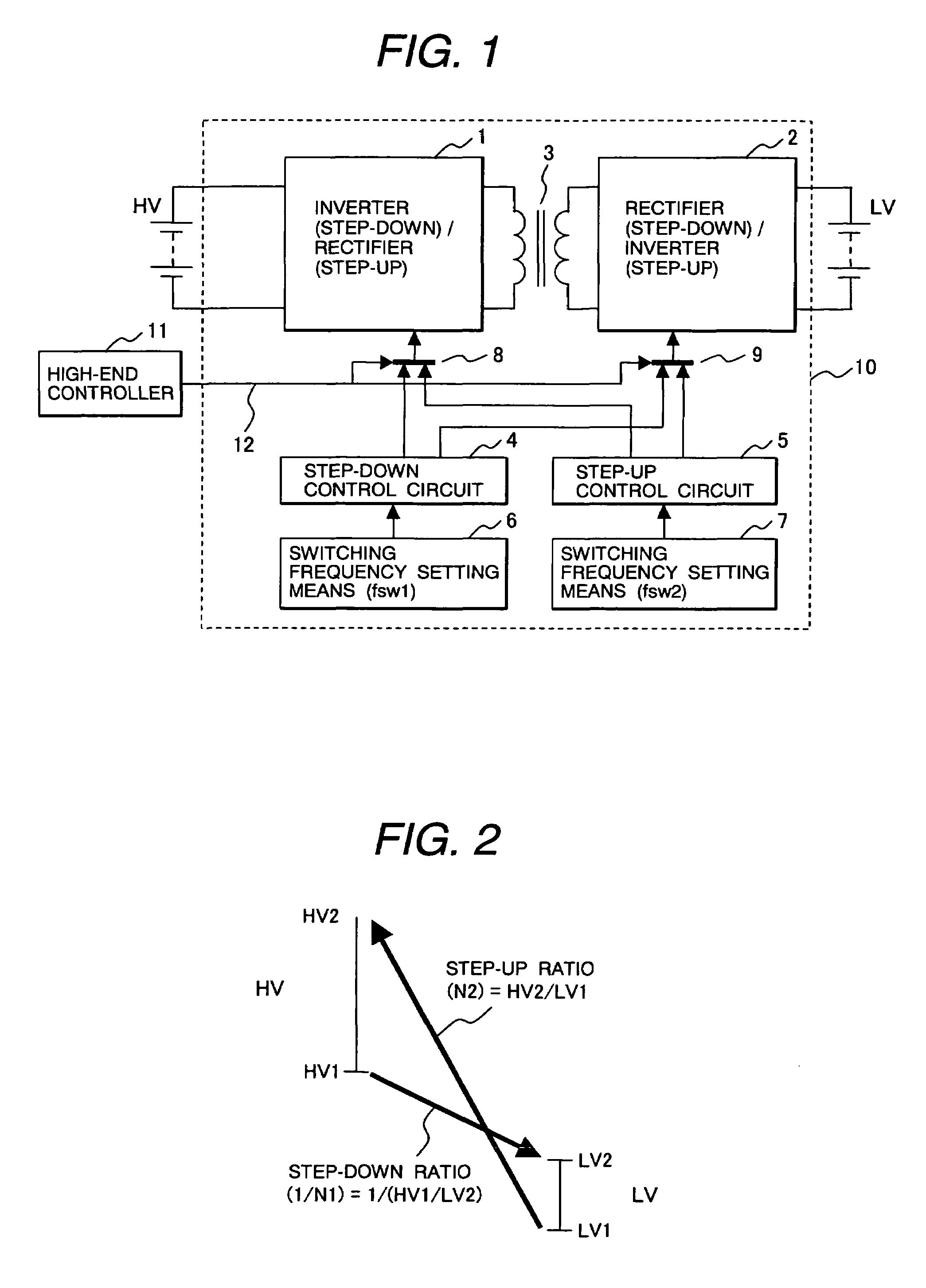
[0045]FIG. 1 shows the entire structure of a bi-directional DC-DC converter according to a first embodiment of the present invention. The main circuits in FIG. 1 are a high-voltage DC power supply HV, a low-voltage DC power supply LV, a main high-voltage circuit 1 having a switching means, and a main low-voltage circuit 2 having a switching means, and a transformer 3.
[0046]Provided as control circuits are a step-down control circuit 4 for dropping the voltage from the HV side to the LV side, a step-up control circuit 5 for boosting the voltage, a switching frequency setting means 6 for a switching signal generated by the step-down control circuit 4, and a frequency setting means 7 for the step-up control circuit 5. Selectors 8 and 9 are also included; the selector 8 selectively selects a control signal sent from the step-down control circuit 4 and a control signal sent from the step-up control circuit 5 and sends the selected signal to the main high-voltage circuit 1; the selector 9...
second embodiment
[0067]FIG. 6 shows the entire structure of a bi-directional DC-DC converter according to a second embodiment of the present invention. The functional parts in FIG. 6 that are identical to the corresponding ones in FIG. 1 are assigned the same reference numerals to eliminate duplicate description. FIG. 6 differs from FIG. 1 in that a switching circuit 13 that switches between the switching frequencies fsw1 and fsw2 is provided. A switching frequency setting means 14 sets the switching frequency fsw1 according to an fsw1 switching signal 16 from the switching circuit 13. A switching frequency setting means 15 sets the switching frequency fsw2 according to an fsw2 switching signal 17 from the switching circuit 13. The switching circuit 13 is structured so that it receives the step-down / step-up control switching signal 12 sent from the high-end controller 11, a voltage signal 18 from the high-voltage DC power supply HV, and a voltage signal 19 from the low-voltage DC power supply LV. Th...
third embodiment
[0072]FIG. 7 shows the entire structure of a bi-directional DC-DC converter according to a third embodiment of the present invention. The functional parts in FIG. 7 that are identical to the corresponding ones in FIG. 1 are assigned the same reference numerals to eliminate duplicate description. FIG. 7 differs from FIG. 1 in that the structure in FIG. 6 is further modified; an operation switching circuit 22 is provided, which receives a control signal 21 from the high-end controller 11 and switches the operation of the DC-DC converter 23.
[0073]The control signal 21 from the high-end controller 11 includes a command for indicating a step-down or step-up operation and frequency setting information about the switching frequency fsw1 during the step-down operation and the switching frequency fsw2 during the step-up operation. The operation switching circuit 22 generates a step-down / step-up control switching signal 12 according to the control signal 21 from the high-end controller 11, an...
PUM
 Abstract
Description
Claims
Application Information
 - R&D
- Intellectual Property
- Life Sciences
- Materials
- Tech Scout
- Unparalleled Data Quality
- Higher Quality Content
- 60% Fewer Hallucinations
Browse by: Latest US Patents, China's latest patents, Technical Efficacy Thesaurus, Application Domain, Technology Topic, Popular Technical Reports.
© 2025 PatSnap. All rights reserved.Legal|Privacy policy|Modern Slavery Act Transparency Statement|Sitemap|About US| Contact US: help@patsnap.com


