
Apparatus and method for exposing a substrate to UV radiation using asymmetric reflectors

a technology of asymmetric reflectors and substrates, applied in the direction of optical radiation measurement, instruments, therapy, etc., can solve the problems of consuming significant processing time, and affecting the overall fabrication process, so as to reduce light loss

Active Publication Date: 2010-04-06
APPLIED MATERIALS INC
View PDF50 Cites 333 Cited by
  • Summary
  • Abstract
  • Description
  • Claims
  • Application Information

AI Technical Summary

Benefits of technology

The patent text describes a substrate processing tool that uses ultraviolet radiation to cure dielectric materials on a substrate. The tool includes a UV radiation lamp that generates and transmits ultraviolet radiation to the substrate. The substrate is supported by a substrate support, and the UV radiation lamp is positioned above the substrate. The UV radiation lamp can be rotated to provide a more uniform distribution of ultraviolet radiation over the substrate. The tool also includes a reflector that redirects the ultraviolet radiation towards the substrate, improving the curing process. The technical effects of the invention include improved curing of dielectric materials on substrates and more uniform distribution of ultraviolet radiation during the curing process.

Problems solved by technology

Either of these forms of water incorporation are generally undesirable.
Also, in some particular CVD processes, thermally unstable organic fragments of sacrificial materials need to be removed.
Conventional thermal anneal steps are generally of relatively long duration (e.g., often between 30 min to 2 hrs.) and thus consume significant processing time and slow down the overall fabrication process.
The use of UV radiation for curing and densifying CVD films can reduce the overall thermal budget of an individual wafer and speed up the fabrication process.

Method used


Image

  • Apparatus and method for exposing a substrate to UV radiation using asymmetric reflectors
  • Apparatus and method for exposing a substrate to UV radiation using asymmetric reflectors
  • Apparatus and method for exposing a substrate to UV radiation using asymmetric reflectors

Examples


Embodiment Construction

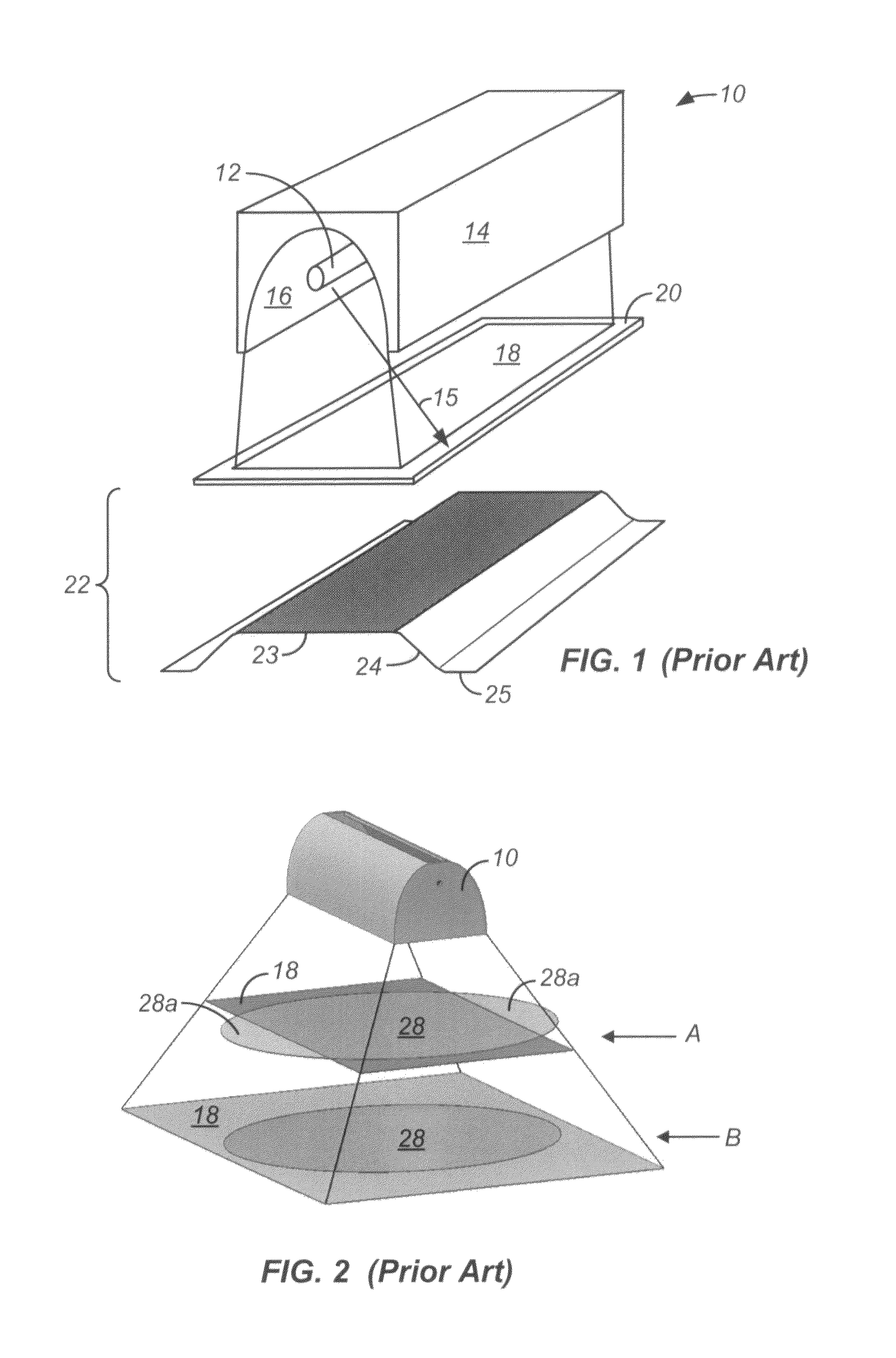
[0048]FIG. 1 is a perspective view of a prior art microwave UV lamp 10 that illustratively depicts an irradiance level of radiation generated by the lamp over a substantially rectangular exposure area. Lamp 10 includes an elongated UV bulb 12 mounted within a housing 14. Housing 14 includes a reflector 16 that faces UV bulb 12 and directs UV radiation into a flood pattern 18 over a substrate 20. Reflector 16 is placed inside a resonant cavity, which limits the size and shape of the reflector.

[0049]While reflector 16 reflects the majority of radiation (within selected wavelengths) that strikes its surface within flood pattern 18, some radiation escapes the reflector surface and falls outside the boundaries of pattern 18. An example of such radiation is illustrated in FIG. 1 by radiation path 15. The intensity of radiation generated by lamp 10 both within and outside flood pattern 18 is illustrated conceptually (in a simplified manner) in bottom portion 22 of FIG. 1. As shown in botto...


PUM


Abstract

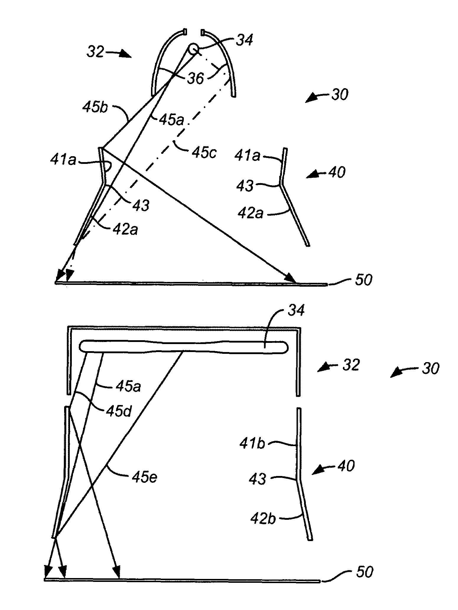
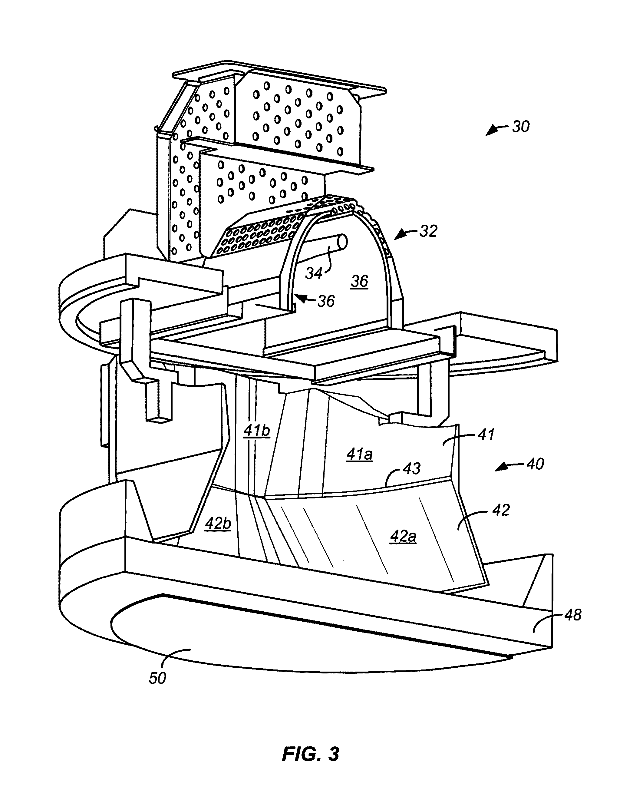
Embodiments of the invention relate generally to an ultraviolet (UV) cure chamber for curing a dielectric material disposed on a substrate and to methods of curing dielectric materials using UV radiation. A substrate processing tool according to one embodiment comprises a body defining a substrate processing region; a substrate support adapted to support a substrate within the substrate processing region; an ultraviolet radiation lamp spaced apart from the substrate support, the lamp configured to transmit ultraviolet radiation to a substrate positioned on the substrate support; and a motor operatively coupled to rotate at least one of the ultraviolet radiation lamp or substrate support at least 180 degrees relative to each other. The substrate processing tool may further comprise one or more reflectors adapted to generate a flood pattern of ultraviolet radiation over the substrate that has complementary high and low intensity areas which combine to generate a substantially uniform irradiance pattern if rotated. Other embodiments are also disclosed.

Description

CROSS-REFERENCES TO RELATED APPLICATIONS[0001]This application claims priority to U.S. Provisional Application No. 60 / 783,421, filed Mar. 17, 2006; U.S. Provisional Application No. 60 / 816,660, filed Jun. 26, 2006; U.S. Provisional Application No. 60 / 816,723, filed Jun. 26, 2006; and U.S. Provisional Application No. 60 / 886,906, filed Jan. 26, 2007 are herein incorporated herein by reference in their entirety.[0002]This application is related to U.S. application Ser. No. 11 / 686,881, filed Mar. 15, 2007; and to U.S. application Ser. No. 11 / 686,878, filed Mar. 15, 2007; and to U.S. application Ser. No. 11 / 686,897, filed Mar. 15, 2007; and to U.S. application Ser. No. 11 / 686,901, filed Mar. 15, 2007. Each of the applications listed above are assigned to Applied Materials, Inc., the assignee of the present invention and are hereby incorporated by reference.BACKGROUND OF THE INVENTION[0003]Materials such as silicon oxide (SiOx), silicon carbide (SiC) and carbon doped silicon oxide (SiOCx) ...

Claims


Application Information

Patent Timeline
Patent Type & Authority Patents(United States)
IPC IPC(8): H01J49/00H01J49/44
CPCB82Y10/00G21K1/062H01L21/67115G21K2201/064G21K2201/067G21K2201/061
Inventor KASZUBA, ANDRZEIROCHA-ALVAREZ, JUAN CARLOSBALUJA, SANJEEVCHO, TOM K.M'SAAD, HICHEMHENDRICKSON, SCOTT A.HO, DUSTIN W.NOWAK, THOMAS
Owner APPLIED MATERIALS INC
Learn More