
Fiber optic sensors for composite pressure tanks with micro bend pinch points

a technology of fiber optic sensors and composite pressure tanks, which is applied in the direction of optical radiation measurement, liquid/fluent solid measurement, instruments, etc., can solve the problem that the tank must be removed from service for testing, and achieve the effect of improving the safe operation of the composite tank and substantial maintenance cost savings

Inactive Publication Date: 2010-03-30
KNAPP RONALD H
View PDF6 Cites 15 Cited by
  • Summary
  • Abstract
  • Description
  • Claims
  • Application Information

AI Technical Summary

Benefits of technology

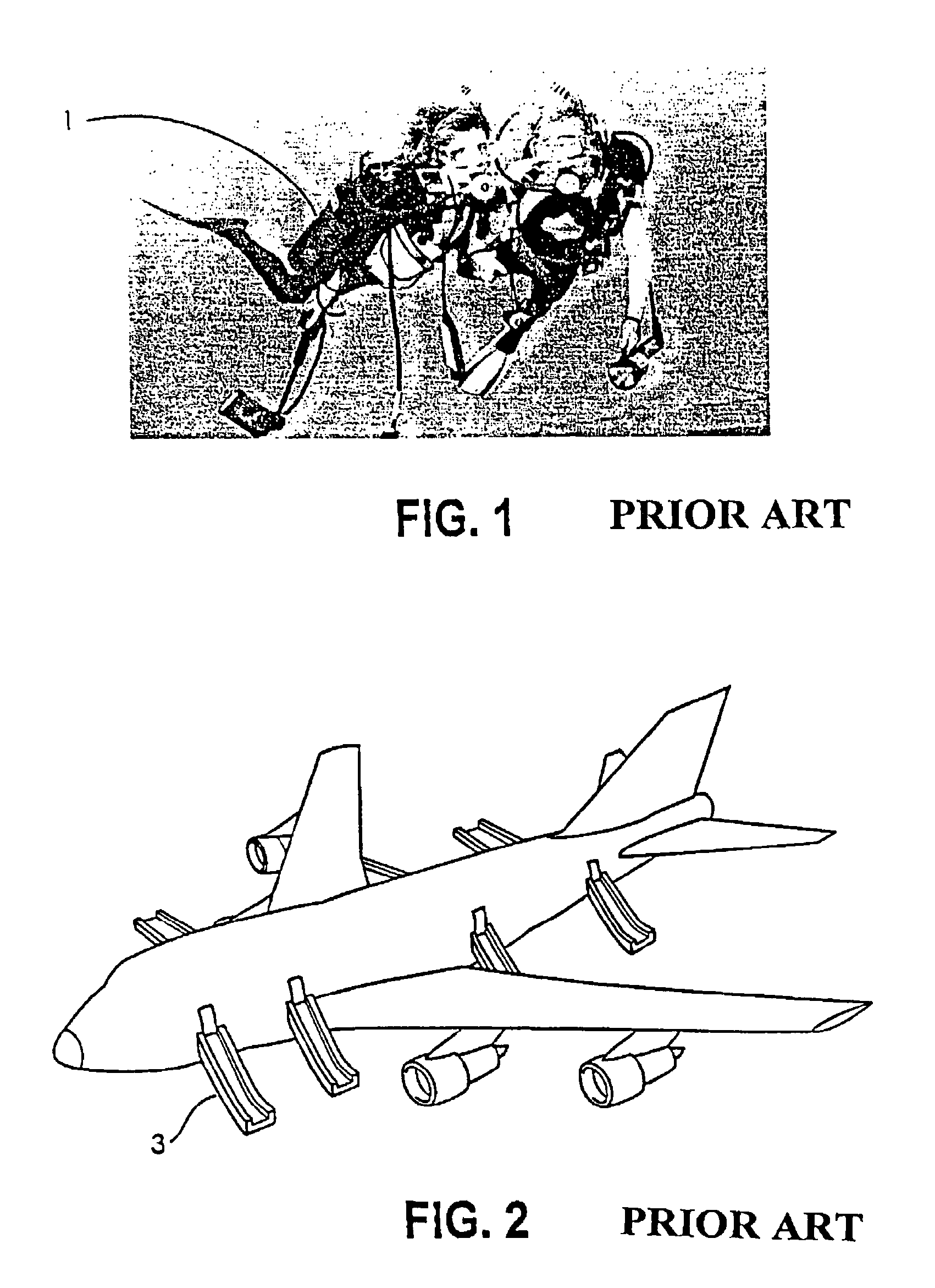
[0007]The invention provides a Low-cost Fiber-Optic Sensor System for Composite Pressure Tanks to detect structural degradation of composite material pressure tanks. Light power attenuation in an embedded optical fiber is used to measure tank volume change and can replace hydrostatic tank testing. Current U.S. Department of Transportation rules require that all pressure tanks be hydrostatically tested to verify structural integrity. This means that tanks have to be removed from service for testing. With the invention, testing can be done in-situ. For some applications such as composite LNG tanks used on vehicles or emergency inflation devices used on aircraft for escape ramps, etc., in-situ testing offers substantial maintenance cost savings. Also, because of the simplicity of the test procedure, more frequent structural checks can be made economically to improve the safe operation of composite tanks.
[0016]Finally, the tank with attached optical fiber sensor and optical connectors is over-wrapped with composite material using normal fabrication techniques. In the case of cylindrical tanks, this is accomplished by filament-winding the tank. The installation of the fiber optic sensor is economical and does not require composite pressure tank manufacturers to alter substantially standard fabrication techniques.
[0018]By integrating a simple, low-cost optical fiber sensor into the composite shell, tanks can be checked easily for structural integrity each time the cylinder is refilled with gas. The opportunity to provide such continuity in structural health monitoring should have a significant positive impact on obtaining DOT certifications, extending product useful life, and establishing buyer confidence.
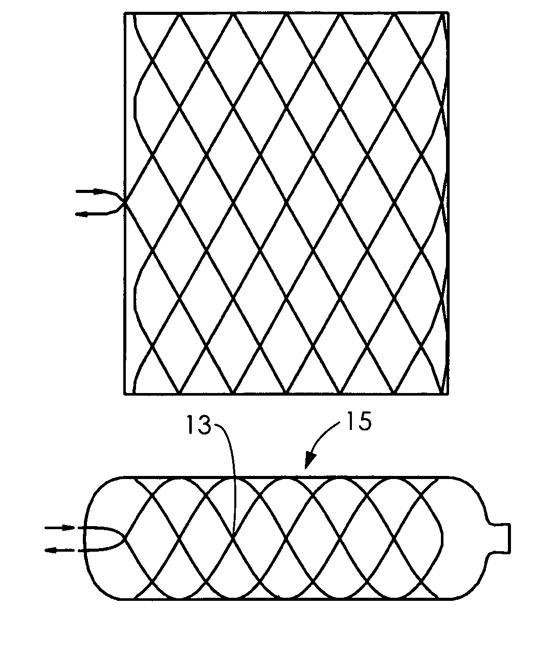
[0019]The design challenge has been to create an embedded Fiber Optical Sensor System (FOSS) that can detect structural faults without precipitating structural degradation of the composite material. The manufacturing challenge has been to determine a means of integrating the sensor system into the tank fabrication process. An embedded optical fiber microbend sensor, a modified type ST connector and a handheld optical laser and power meter constitute the optical sensor system that is used to monitor internal defects in the composite structure. Low-cost is obtained by using readily available optical components and a simple installation procedure, and robustness is provided by embedding the optical fiber sensor and encasing the optical connector in a metal housing.
[0021]The microbend sensor system can simulate conventional hydrostatic tank testing where tank dilatation (volume change) is measured in response to internal pressure. By wrapping an optical fiber around the inner metallic liner of a tank, the optical fiber will be stretched along its entire length and subjected to microbending at locations where it contacts itself. This mechanical action must be designed to produce sufficient light power attenuation in response to applied internal pressure. The light attenuation will be a measure of the dilatation of the tank, and therefore can be used as a simpler replacement to conventional hydrostatic testing.

Problems solved by technology

This means that tanks have to be removed from service for testing.

Method used


Image

  • Fiber optic sensors for composite pressure tanks with micro bend pinch points
  • Fiber optic sensors for composite pressure tanks with micro bend pinch points
  • Fiber optic sensors for composite pressure tanks with micro bend pinch points

Examples


Embodiment Construction

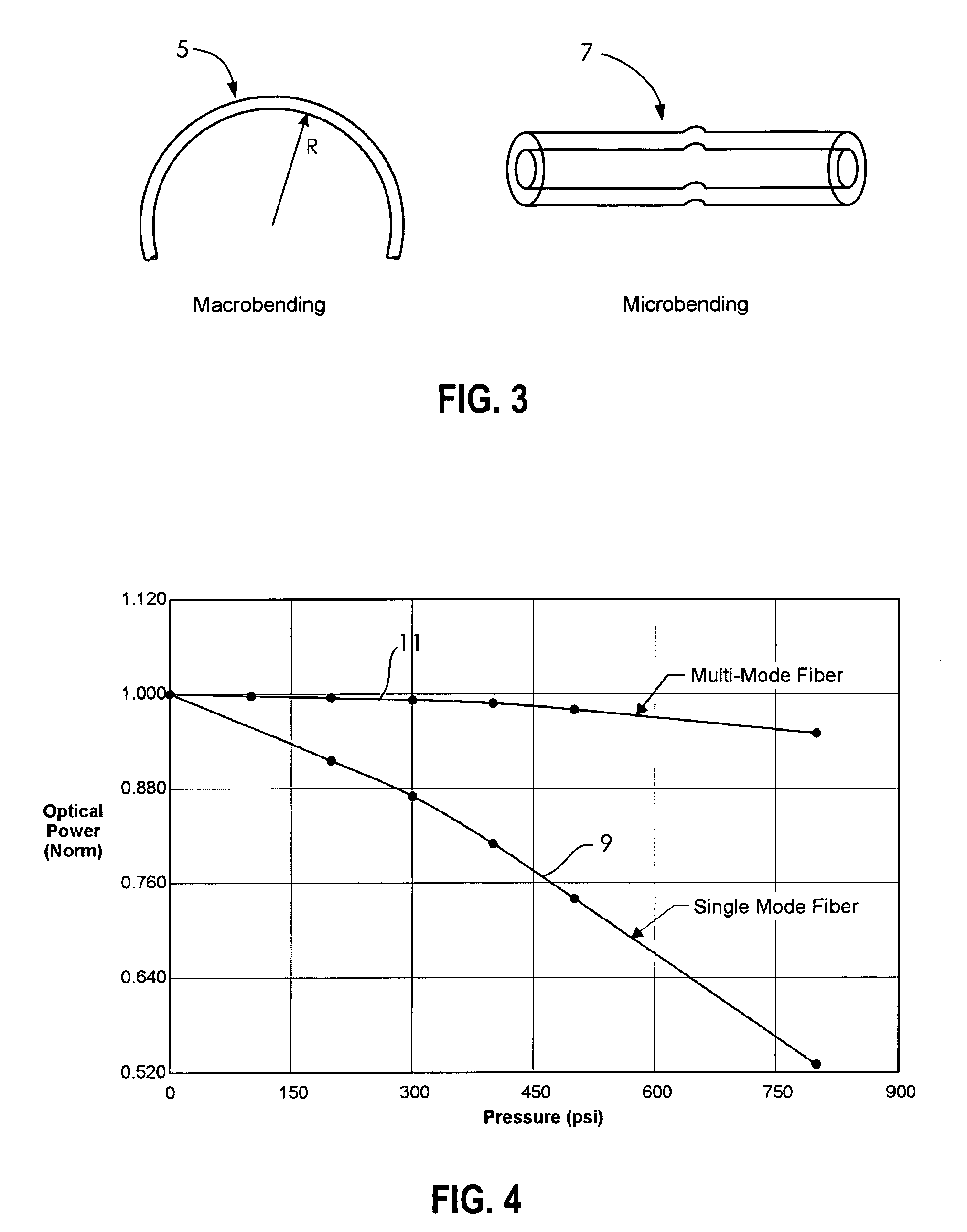
[0054]Optical fibers are manufactured for specific wavelengths of light that maximize light power transmitted through the fiber and minimize light loss as the fiber is bent. This approach is needed for telecommunication fibers where light must be transmitted over long distances. For an optical sensor, however, a different approach must be taken. Since the sensor will function as a microbend sensor, an optical fiber that is sensitive to fiber bending should be used.

[0055]Transmitted light power is lost in response to microbending. The very small bend radius associated with microbending diminishes power when the highest-order guided mode in the fiber core is coupled to the first cladding (radiation) mode, which then is rapidly attenuated. FIG. 3 compares macrobending 5 and microbending 7. The curvatures of the bent fiber are very small, and very abrupt, for microbending than for the more gentle macrobending.

[0056]Fibers are produced as single mode or multi-mode carriers of light. As s...


PUM


Abstract

A low-cost fiber-optic sensor system for composite pressure tanks detects structural degradation of composite material pressure tanks. Light power attenuation in embedded optical fiber simulates tank volume change and replaces hydrostatic tank testing. Current U.S. Department of Transportation rules require that all pressure tanks be hydrostatically tested to verify structural integrity. Tanks do not have to be removed from service for testing. With the invention, testing can be done in-situ. For composite LNG tanks used on vehicles or emergency inflation devices used on aircraft for escape ramps, in-situ testing offers substantial maintenance cost savings. because of the simplicity of the test procedure, more frequent structural checks can be made economically to improve the safe operation of composite tanks.

Description

[0001]This application claims the benefit of U.S. Provisional Application Ser. No. 60 / 455,587 filed Mar. 19, 2003.[0002]This invention was made with Government support under Contract No. 44751 awarded by the Department of Transportation. The Government has certain rights in this invention.BACKGROUND OF THE INVENTION[0003]Lightweight composite SCBA (Self-Contained Breathing Apparatus) pressurized cylinders are in wide use in the firefighting, medical, aviation and transportation markets. Composite material (S-2 glass / epoxy, Kevlar / epoxy, carbon / epoxy, etc.) are used for life support gas cylinders, aircraft inflatables, oxygen supply applications, life support cylinders, recreational SCUBA tanks 1 (FIG. 1) and alternative fuel vehicles.[0004]Composite pressure tanks are manufactured by overwrapping aluminum liners with hoop-wrapped or full-wrapped (axial+hoop) shells. The aluminum liner serves as an impermeable gas barrier and the composite shell provides the structure that resists th...

Claims


Application Information

Patent Timeline
Patent Type & Authority Patents(United States)
IPC IPC(8): G01J1/04G01J1/42G01J5/08
CPCG01D11/245G01L1/245G01L11/025G01D5/35345G01M5/0091G01D5/35374G01M5/0041G01D5/35341
Inventor KNAPP, RONALD H.
Owner KNAPP RONALD H
Learn More