
System and method for coordinating cluster state information

a cluster state and information technology, applied in the field of clustered file servers, can solve the problems of component failure that would not prevent either filer from serving its normal workload, and initiation of a takeover process, so as to prevent data integrity loss

Active Publication Date: 2010-03-23
NETWORK APPLIANCE INC
View PDF32 Cites 23 Cited by
  • Summary
  • Abstract
  • Description
  • Claims
  • Application Information

AI Technical Summary

Benefits of technology

The solution ensures high availability and reliability by preventing data loss during failures and connectivity issues, tolerating multiple node failures, and providing effective warnings for sequential consistency, while being flexible with dynamically changing hardware configurations.

Problems solved by technology

Nonvolatile memory shadowing is not performed at this time because, in general, the failed filer is unable to receive the memory shadowing while it is awaiting repair or reboot.
Additionally, there may be a failure of a component, for example the cluster interconnect that links file servers in a cluster, which thereby prevents the non-volatile memory shadowing process from operating correctly.
However, component failure would not prevent either filer from serving its normal workload.
A common problem is presented in each of these situations namely, that there are certain useful recovery actions that each filer may perform, but it is critical that if one action should take place an otherwise proper action by the other filer must be prevented from occurring.
Alternatively, Filer A may fail, and then Filer B may takeover the workload of Filer A. However, if Filer B takes over the workload of Filer A, then Filer A must not reboot and resume its workload until the orderly transfer of workload back from Filer B is completed.
Second, the failure of the cluster interconnect may cause the “non-volatile memory shadowing” process to be stopped.
The same or similar failure may be perceived as a loss of one filer by the other, leading to the initiation of a takeover process.
But if Filer A decides to continue service with the “non-volatile memory shadowing” disabled, then Filer B must not do a takeover of the workload of Filer A because it no longer processes a valid copy of all the necessary information.
Three causes are of particular interest, namely, the loss of information due to concurrent access by two filer servers, the loss of information due to device failure, such as disk failure, and the loss of information due to loss of some connectivity from one or more filer servers to one or more devices.
A noted disadvantage of the mailbox system is apparent when the file servers of the cluster are utilizing synchronous mirroring (e.g., when a set of data is stored on two distinct sets of physical storage devices) or when the file servers of a cluster are geographically separated.
In known disk mailbox implementations, the information most recently stored by one file server is not guaranteed to be retrieved by the other file server in all possible cases of failure.
The partition in space problem occurs when there are failures of the connectivity between file servers and storage devices that allow different file servers to have access to different sets of storage devices at the same time.
The partition in space problem is likely to occur in a geographically separated environment, due to the complexities of communication over long distances and the greater likelihood of communication equipment failure.
The partition in time problem occurs when connectivity is lost to one set of devices as a result of a power failure or other failures to the storage fabric.
Thus, by using known mailbox systems, it is possible for data integrity to be lost due to either a partition in time or partition in space problem as described above.

Method used


Image

  • System and method for coordinating cluster state information
  • System and method for coordinating cluster state information
  • System and method for coordinating cluster state information

Examples


Embodiment Construction

[0034]A. File Server Cluster Environment

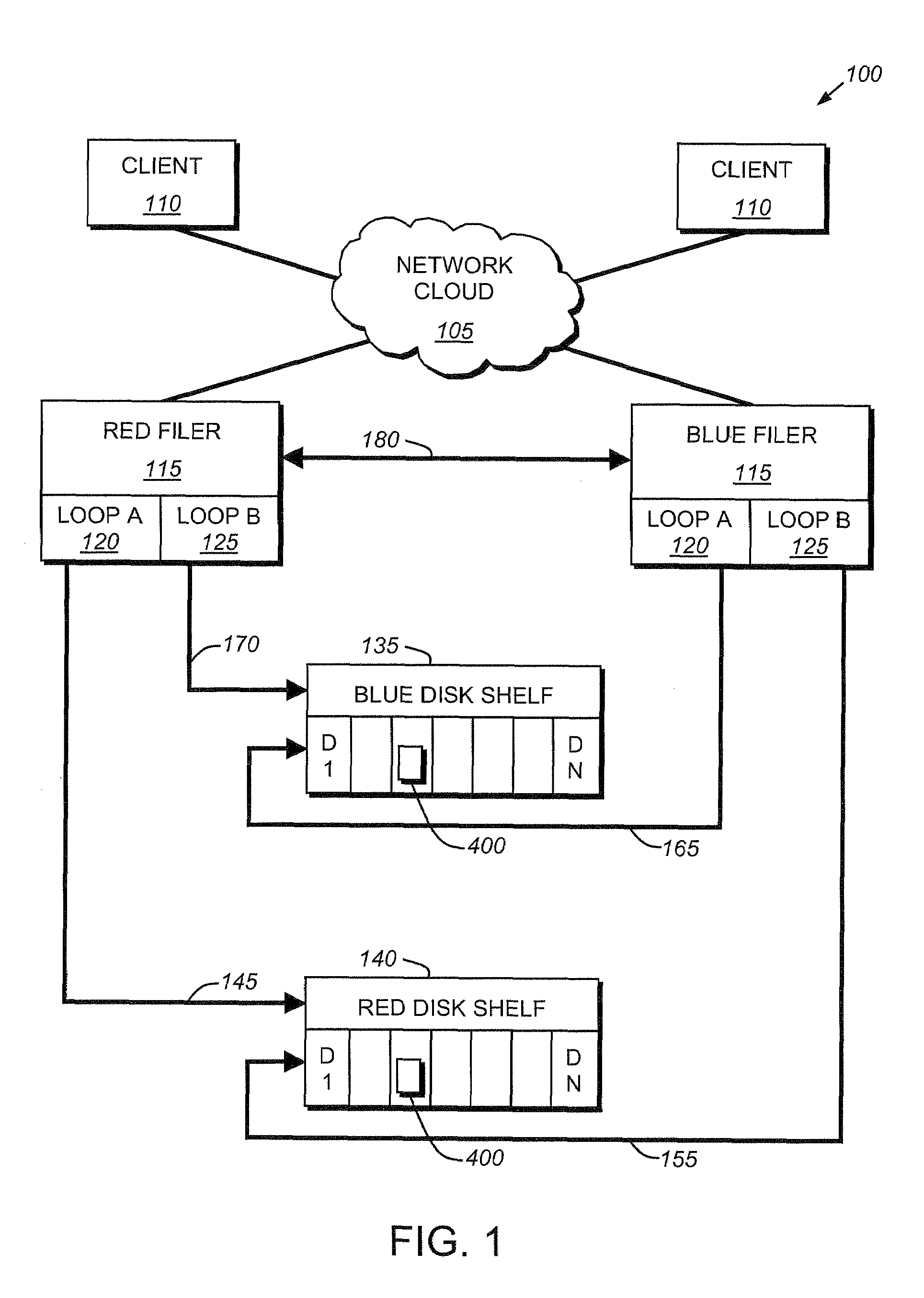
[0035]FIG. 1 is a block diagram of a file server cluster environment 100 having connected as two nodes in the file system cluster two file servers 115. In accordance with known failover techniques, Red Filer and Blue Filer provide takeover protection to each other when one fails. It should be understood that while only two filers and two disk shelves are shown in this illustrative cluster configuration, it is expressly contemplated that multiple filers and disk shelves may be connected in a cluster configuration and provide takeover for each other.

[0036]A plurality of clients 110 are connected to a network cloud 105. The network cloud can be comprised of any acceptable networking architecture including, for example, a local area network (LAN), a wide area network (WAN), a virtual private network (VPN) or any other networking architecture including, for example the Internet. A set of file servers, or filers, is also connected to the network clo...


PUM


Abstract

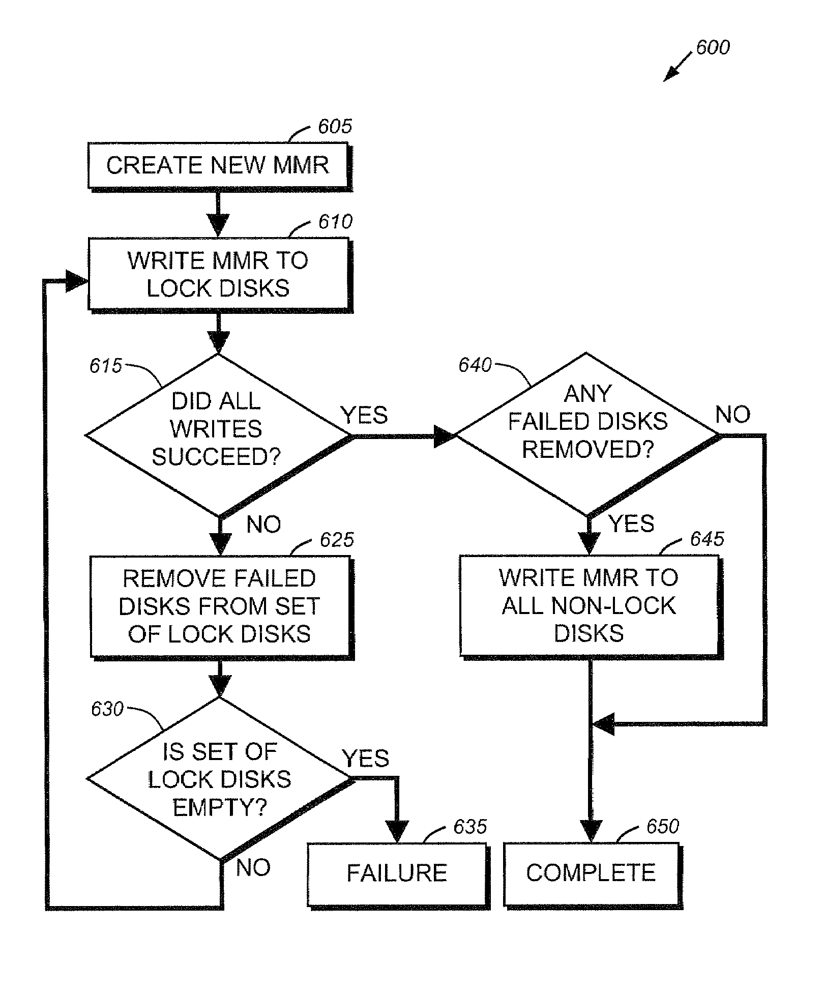
A method for managing a cluster of file servers is disclosed. The method has the first step of writing coordinating information for a plurality of servers of the cluster of servers to a master mailbox record, the master mailbox record written to a specific location on each disk of a set of lock disks, the set of lock disks having a plurality of disks, the plurality of disks chosen so that in the event of failure of a server of the plurality of servers, at least one lock disk will be available to the remaining servers. The method has the second step of writing a second copy of eth coordinating information to the master mailbox record of the set of lock disks.

Description

RELATED APPLICATIONS[0001]This application is a continuation of U.S. patent application Ser. No. 10 / 378,400 filed on Mar. 3, 2003, now issued as U.S. Pat. No. 7,231,489 for SYSTEM AND METHOD FOR COORDINATING CLUSTER STATE INFORMATION.FIELD OF THE INVENTION[0002]The present invention relates to clustered computing environments, and, more specifically to clustered file servers.BACKGROUND OF THE INVENTION[0003]A file server is a computer that provides file service relating to the organization of information on writeable persistent storage devices, such as memories, tapes or hard disks. The file server or filer may be embodied as a storage system including an operating system that implements a file system to logically organize the information as a hierarchical structure of directories and files on, e.g., the disks. Each “on-disk” file may be implemented as a set of data structures, e.g., disk blocks, configured to store information, such as the actual data for the file. A directory, on ...

Claims


Application Information

Patent Timeline
Patent Type & Authority Patents(United States)
IPC IPC(8): G06F12/00G06F15/167
CPCG06F11/2023G06F11/2035G06F3/0601G06F11/1441G06F11/2071G06F2003/0697G06F3/067G06F3/0637G06F3/0689G06F3/0619
Inventor LARSON, RICHARD O.ROWE, ALAN L.SEN SARMA, JOYDEEP
Owner NETWORK APPLIANCE INC
Learn More