
Method and system of fault powered supply voltage regulation

a technology of power supply voltage regulation and fault, applied in the field of circuit breakers, can solve the problems of power supply interruption, delay, and unpredictable voltage levels across solenoid, and achieve the effects of minimizing voltage regulation ripple, minimizing power supply peak overshoot, and wide operating rang

Active Publication Date: 2010-03-23
SQUARE D CO
View PDF29 Cites 8 Cited by
  • Summary
  • Abstract
  • Description
  • Claims
  • Application Information

AI Technical Summary

Benefits of technology

"The patent describes a fault-powered voltage regulation control algorithm that can be used in a variety of breaker products. The algorithm minimizes power supply peak overshoot, voltage regulation ripple, and maintains stored energy trip voltages. This results in improved system performance while reducing the requirements for expensive external hardware components. The algorithm also includes a backup trip detection system and can be extended to other similar trip unit design platforms. The algorithm is designed to achieve power supply startup stability and improve power supply ripple performance after startup. The algorithm reverts to a charge-only state to avoid nuisance tripping if the fault-powered signals decrease below the lowest pickup thresholds."

Problems solved by technology

A circuit breaker may be tripped by an overload or short circuit, which causes an interruption of power to the load.
If the solenoid is not sufficiently powered or not powered rapidly enough, when a trip event needs to occur, a delay can be introduced.
When transitioning between un-powered and powered modes of the circuit breaker, the voltage levels across the solenoid can be unpredictable, leading to nuisance trips such as when fault powered current falls below the lowest pickup threshold.

Method used


Image

  • Method and system of fault powered supply voltage regulation
  • Method and system of fault powered supply voltage regulation
  • Method and system of fault powered supply voltage regulation

Examples


Embodiment Construction

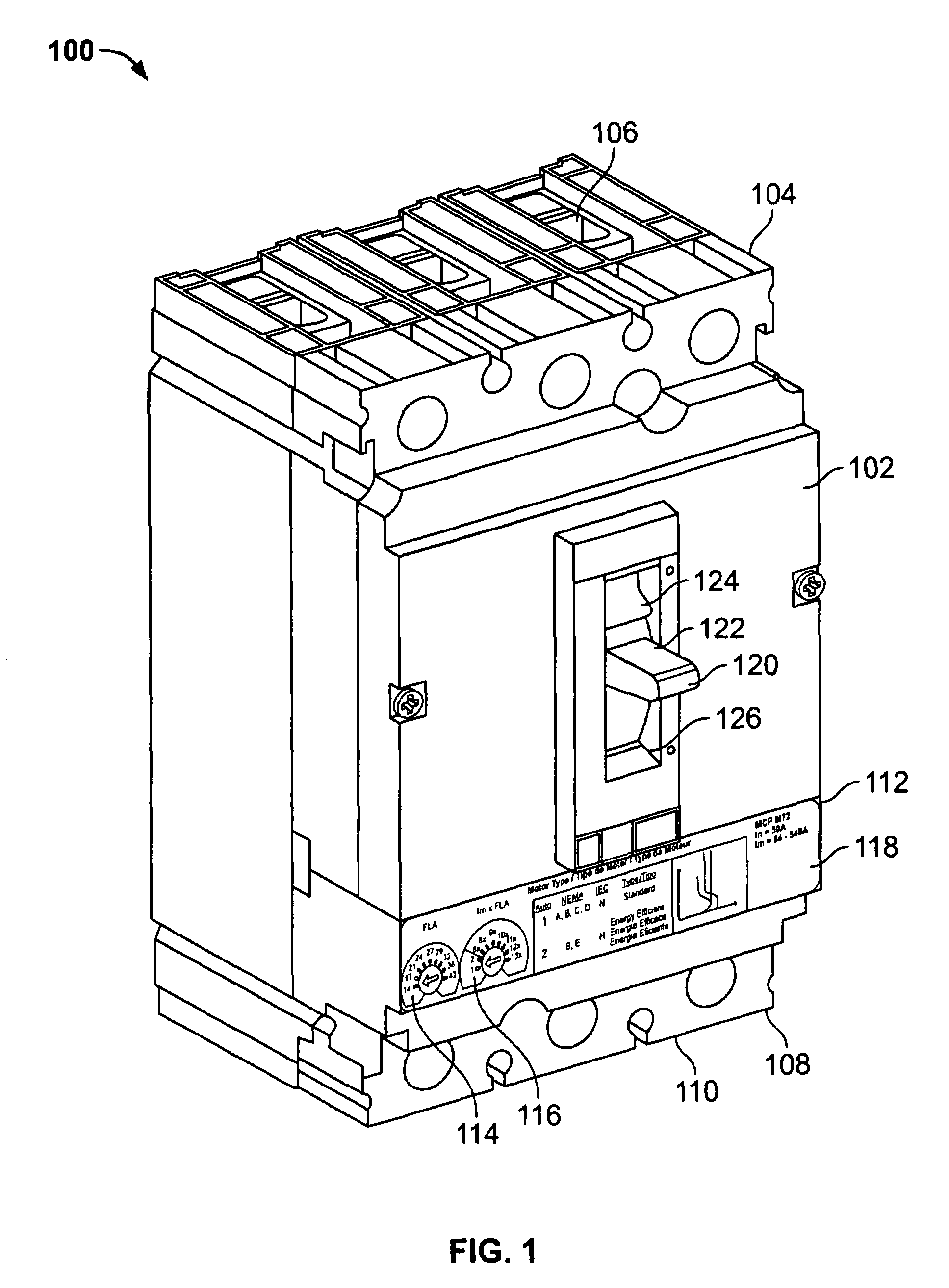
[0020]Turning now to FIG. 1, an electronic motor circuit protector 100 is shown. The motor circuit protector 100 includes a durable housing 102 including a line end 104 having line terminals 106 and a load end 108 having load lugs or terminals 110. The line terminals 106 allow the motor circuit protector 100 to be coupled to a power source and the load terminals 110 allow the motor circuit protector 100 to be coupled to an electrical load such as a motor as part of a motor control center (“MCC”). In this example the motor circuit protector 100 includes a three-phase circuit breaker with three poles, although the concepts described below may be used with circuit protectors with different numbers of poles, including a single pole.

[0021]The motor circuit protector 100 includes a control panel 112 with a full load ampere (“FLA”) dial 114 and an instantaneous trip point (“Im”) dial 116 which allows the user to configure the motor circuit protector 100 for a particular type of motor to be...


PUM


Abstract

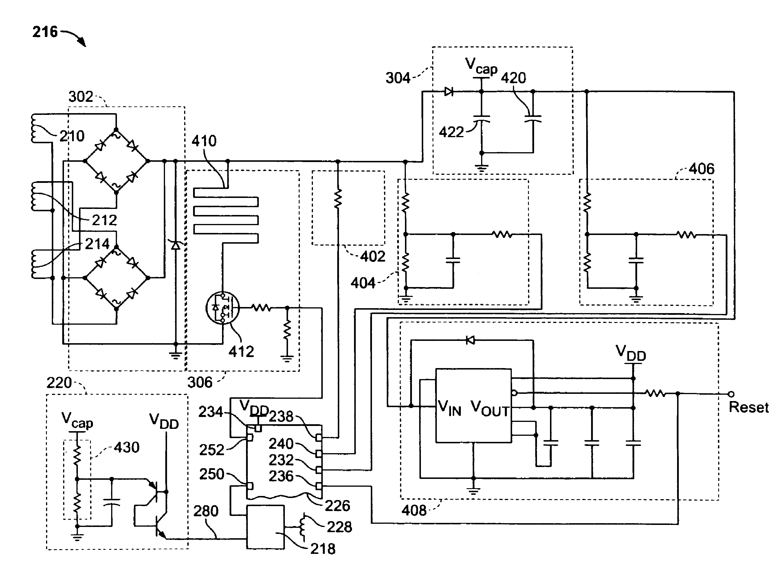
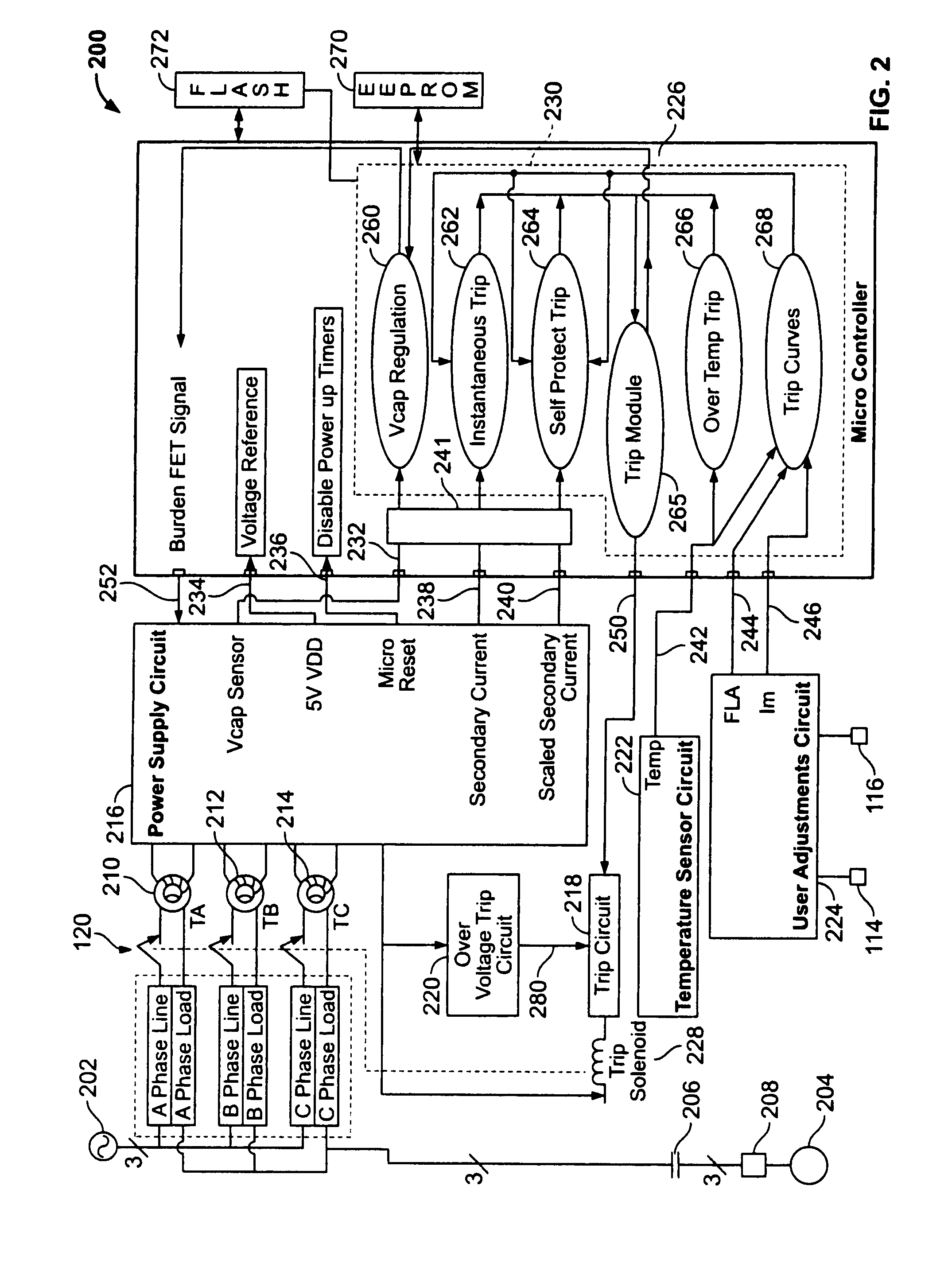
A method and system for supply voltage regulation in a motor circuit protector (MCP) that includes a current transformer coupled to a rectifier and a stored energy circuit. A solenoid is actuated by that circuit when a sufficient voltage is present. A controller having a configurable input is coupled to the stored energy circuit. Upon startup of the motor circuit protector, the controller causes the stored energy circuit to be charged to a startup voltage level via secondary current from the current transformer. The controller periodically interrupts the charging to measure the secondary current to detect fault levels. During startup, the configurable input is set to a comparator input for rapid current measurements. During run mode, the configurable input is set to an A / D input for accurate measurements. The controller measures the voltage of the stored energy circuit while charging it to a power level sufficient to actuate the solenoid.

Description

RELATED APPLICATION[0001]This application claims the benefit of U.S. Provisional Application No. 60 / 831,006, filed Jul. 14, 2006, titled “Motor Circuit Protector,” which is hereby incorporated by reference in its entirety.FIELD OF THE INVENTION[0002]The present invention relates generally to circuit breaker devices, and, in particular, to a fault power supply voltage regulation scheme.BACKGROUND OF THE INVENTION[0003]A fault-powered supply receives a fault current from a line conductor and powers electrical components from the fault current. An important electrical component of some circuit breakers is a solenoid, which must attain a predetermined voltage in order to energize an actuator that causes a trip mechanism of the circuit breaker to trip the circuit breaker. As is well known, a circuit breaker is an automatically operated electro-mechanical device designed to protect conductors from damage caused by an overload or a short circuit. Circuit breakers may also be utilized to pr...

Claims


Application Information

Patent Timeline
Patent Type & Authority Patents(United States)
IPC IPC(8): H02J7/00H02J7/04H02J7/16
CPCH02H1/06H02H7/0822
Inventor DAVISON, WILLIAM C.DUNNE, DAVID JOSEPHMALO, KEVIN JOHNMEEHLEDER, STEVE M.
Owner SQUARE D CO
Learn More