Power supply system

a power supply system and power supply technology, applied in the direction of cable arrangement between relatively moving parts, coupling device connection, cable, etc., can solve the problems of increasing the height of the protector b>50/b>, affecting the operation of the vehicle, and reducing so as to reduce the durability of the wiring harness, the effect of shortening the casing

Inactive Publication Date: 2010-03-23
AISIN SEIKI KK
View PDF8 Cites 11 Cited by
  • Summary
  • Abstract
  • Description
  • Claims
  • Application Information

AI Technical Summary

Benefits of technology

[0020]When the power supply system 61 shown in FIG. 12 is installed on a sliding structure (the sliding door or the sliding seat) with a relatively small sliding length so as to shorten the casing 62 and the compression spring 66, changing of a spring force corresponding to deformation of the compression spring 66 becomes large. Thereby, an unexpected strong spring force generated at some positions of deformation of the compression spring 66 pushes strongly the wiring harness 69, and it may cause reducing durability of the wiring harness 69.
[0021]This strong spring force loads on the sliding structure and operating forces for opening and closing the sliding structure is increased, so that operatability of the vehicle may become worse. When trying to make the change of spring force of the compression spring for overcoming above problems, a whole length of the compression spring 66 must be extended. The extended compression spring 66 increases a size of the casing 62 receiving the compression spring, thereby it will become difficult to install the power supply system in a vehicle.
[0023]According to the above problems, an object of the present invention is to provide a power supply system, which can eliminate generation of an unnecessary strong spring force during sliding operation of a sliding structure, and improve durability of a wiring harness pressed by the spring force and operability of the sliding structure, and additionally can miniaturize the sliding structure and can easily attain a spring having a required spring force, and further additionally can prevent the wiring harness from being damaged when the spring is broken at the worst.How to Attain the Object of the Present Invention
[0027]According to the above, the wiring harness is positioned at an inside of the casing, and the constant force spring is positioned at an outside of the casing. Thus, the constant force spring is separated from the wiring harness. Therefore, if the constant force spring is cracked or broken, the constant force spring does not interfere with the wiring harness, and the wiring harness is prevented from being damaged.

Problems solved by technology

In case that the sliding length of the sliding door 41 is large (i.e. the extra length of the wiring harness is long), there is a problem that a height of the protector 50 increases.
This strong spring force loads on the sliding structure and operating forces for opening and closing the sliding structure is increased, so that operatability of the vehicle may become worse.
The extended compression spring 66 increases a size of the casing 62 receiving the compression spring, thereby it will become difficult to install the power supply system in a vehicle.

Method used


Image

  • Power supply system
  • Power supply system
  • Power supply system

Examples


Embodiment Construction

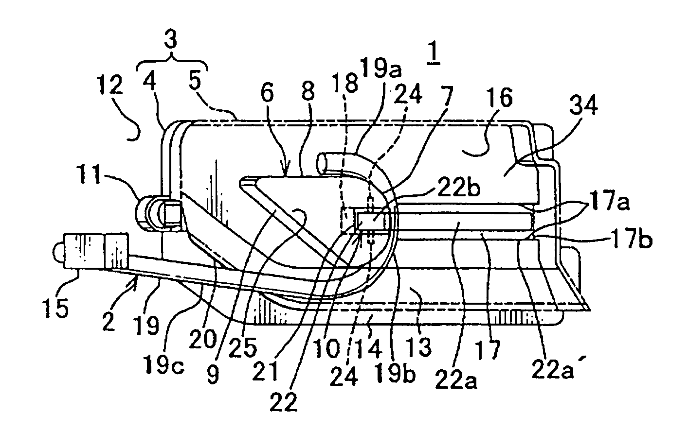
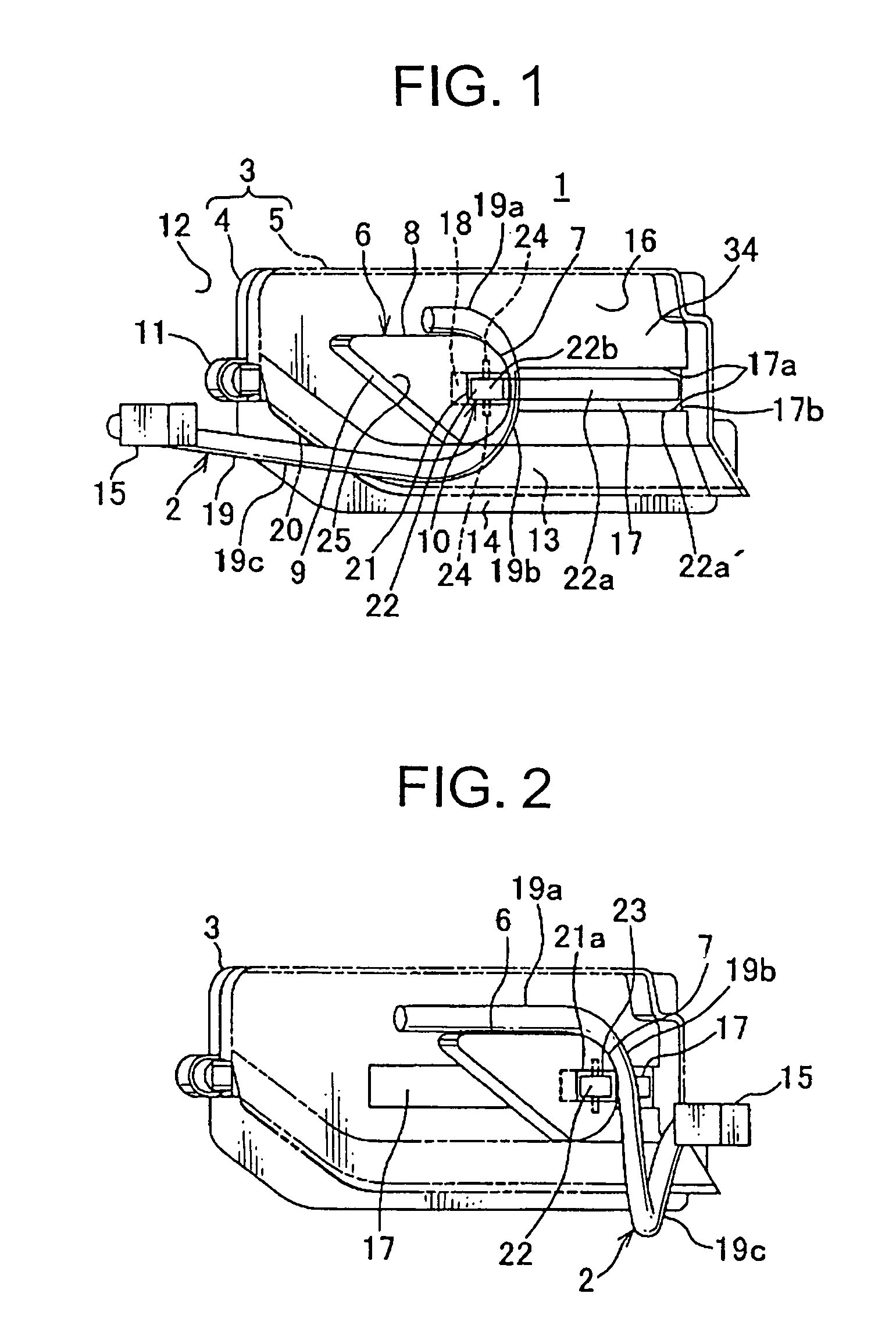
[0046]FIGS. 1, 2 show an embodiment of a power supply system according to the present invention.

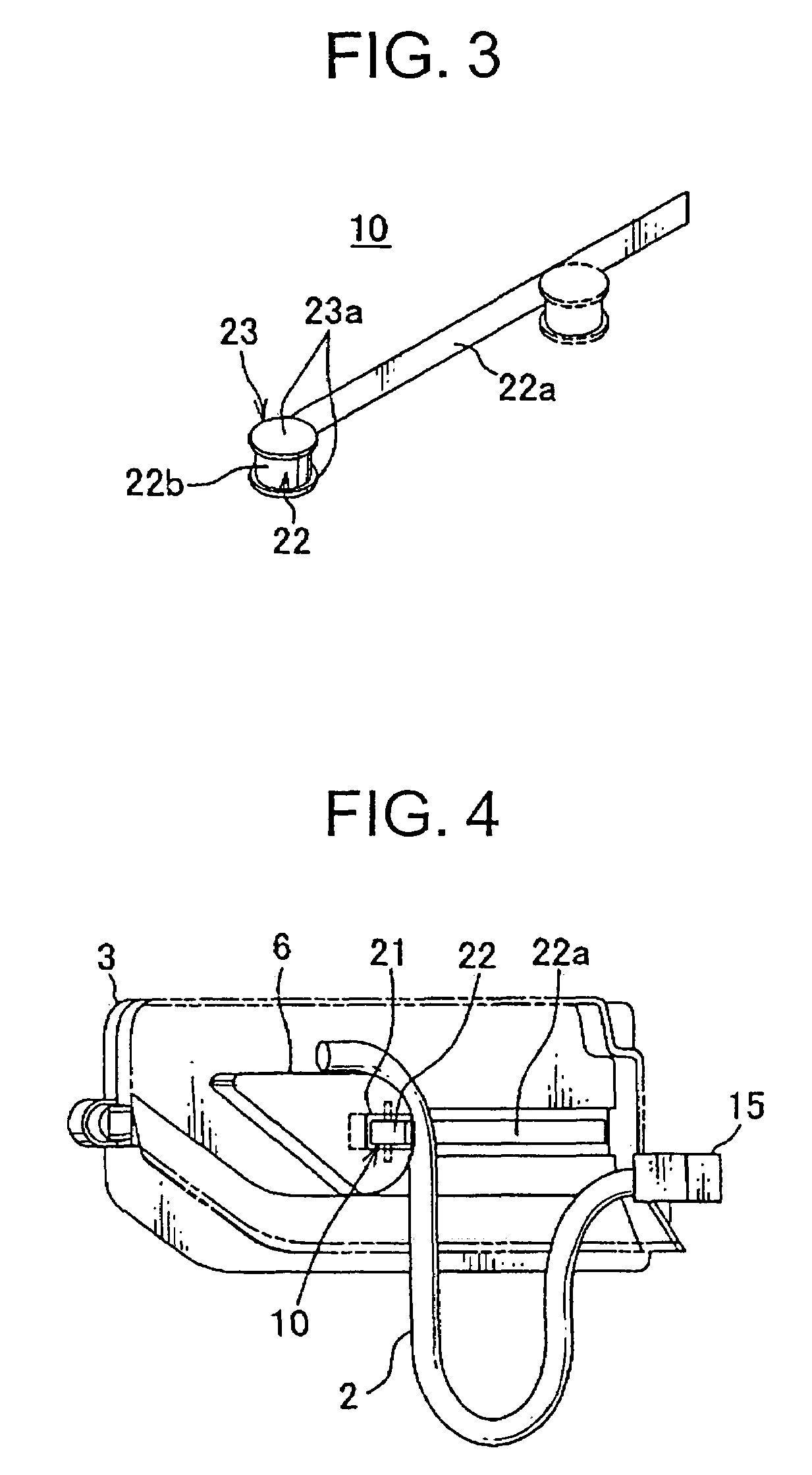
[0047]The power supply system 1 includes a plastic casing 3, a wiring harness 2 bent and arranged movably in the casing 3, a harness supporter 6 having a curved surface 7 providing the wiring harness 2 thereon and being arranged so as to move freely back-and-forth in the casing 3, and a constant force spring 22 biasing the harness supporter 6 so as to absorb an extra length of the wiring harness.

[0048]The casing 3 is formed with a base 4 and a cover 5 (shown with a two-dot chain line). The base 4 and the cover 5 are fixed to each other by a lock device (not shown). The casing 3 includes a harness receiving space 34 surrounded by the base 4 and the cover 5. The base 4 is fixed by a bracket 11 on a door inner panel 12 of a sliding door of a vehicle. A bottom end portion of the cover 5 is curved toward an inside of a vehicle. A long bottom opening 14 is provided between an inside of a curved...


PUM

PropertyMeasurementUnit
spring forceaaaaaaaaaa
lengthaaaaaaaaaa
forceaaaaaaaaaa

Abstract

For improving durability of a wiring harness of a power supply system used in a sliding structure, a power supply system includes a casing; a wiring harness; a harness supporter arranged along a base of the casing so as to move freely back-and-forth in the casing; and a constant force spring arranged along the base of the casing. The wiring harness is bent and wired along an outer surface of the harness supporter, and the harness supporter is biased with a spring force by the constant force spring so as to absorb an extra length of the wiring harness. A winding part of the constant force spring is separated from a harness receiving space of the casing, and an end of the constant force spring led from the winding part is connected and fixed to the harness supporter at an outside of the casing.

Description

CROSS REFERENCE TO RELATED APPLICATIONS[0001]This application is on the basis of Japanese Patent Applications No. 2008-020513 and 2008-152846, the contents of which are hereby incorporated by reference.BACKGROUND OF THE INVENTION[0002]1. Field of the Invention[0003]The present invention relates to a power supply system absorbing an extra length of a wiring harness by using a constant force spring for supplying continuously electric power, for example to a sliding door of a vehicle.[0004]2. Description of the Related Art[0005]FIGS. 11A, 11B show an embodiment of a conventional power supply system (for example, see Patent Document 1).[0006]The power supply system is fixed vertically in a sliding door 41 of a vehicle, and includes a protector (casing) 50 made of synthetic resin for receiving a wiring harness 43 to be bent freely, and a metallic flat spring 44 forcing the wiring harness 43 upwardly in the protector so as to absorb an extra length of the wiring harness 43 by forcing the ...

Claims


Application Information

Patent Timeline
Patent Type & Authority Patents(United States)
IPC IPC(8): H01B7/06
CPCH02G11/00B60R16/027
Inventor TSUBAKI, AKIRASHIRAKI, KENTAROIKEDA, KEI
Owner AISIN SEIKI KK
Why Eureka
Try Eureka