Multi-piece wheel

a multi-piece, wheel technology, applied in the direction of spoked wheels, vehicle components, mechanical vibration separation, etc., can solve problems such as gaps, and achieve the effect of reducing manufacturing costs and facilitating the change of wheel styling

Inactive Publication Date: 2010-03-23
BAGDASARIAN KEN L
View PDF50 Cites 36 Cited by
  • Summary
  • Abstract
  • Description
  • Claims
  • Application Information

AI Technical Summary

Benefits of technology

[0030]The present invention is a multi-piece wheel, which facilitates changing the wheel styling and which can be achieved at a reduced manufacturing cost. The wheel is assembled with multiple pieces of pre-made structural members including an outer wheel ring, a central hub and a multiplicity of spokes. The outer wheel ring is comprised of a generally circular cylindrical wall having a tire receiving inner surface and an outer circular surface. A circular bolt receiving shoulder is transversely affixed onto the outer wheel ring at its outer circular surface, wherein a multiplicity of identical exposed bolt receiving transverse threaded apertures are evenly spaced in a circular pattern in the bolt receiving shoulder to penetrate through the shoulder for connecting of a multiplicity of identical spokes.
[0033]It is an object of the present invention to provide a multi-piece wheel, which is assembled with multiple pieces of pre-made structural members including an outer wheel ring, a central hub and multiple spokes, so that the styling and appearance of the multi-piece wheel can be changed. The present invention also facilitates a reduced cost to manufacture the stylish wheels.
[0034]It is an another object of the present invention to provide an outer wheel ring, which is a generally circular cylindrical wall having an outer circular surface to which is affixed a bolt receiving circular transverse shoulder having a multiplicity of evenly positioned identical transverse bolt receiving threaded apertures for affixing the multiplicity of identical spokes. Each spoke is a generally “T” shaped arcuate structure comprising a round wide transverse first end having a multiplicity of identical transverse bolt receiving holes to connect to an intermediate arcuate elongated member, which in turn is further connected to a narrow spoke second end. Every identical transverse bolt receiving hole on the spoke first end respectively matches a threaded aperture on the wheel ring shoulder, so that the wheel ring can be securely connected to the spokes through affixation of bolts to the corresponding threaded holes of the wheel ring where the bolts respectively penetrate through the corresponding bolt holes of the spokes in assembling the multi-piece wheel of the present invention.
[0036]It is an additional object of the present invention to provide various structural variations, which are related to the connection of the spokes and central hub, so that such variations facilitate construction of various embodiments of the multi-piece wheel of the present invention.

Problems solved by technology

The concern that this patent deals with is there are gaps between the wheel cover and the wheel and which the existence of the gaps is believed to be a problem.

Method used


Image

  • Multi-piece wheel
  • Multi-piece wheel
  • Multi-piece wheel

Examples


embodiment 3

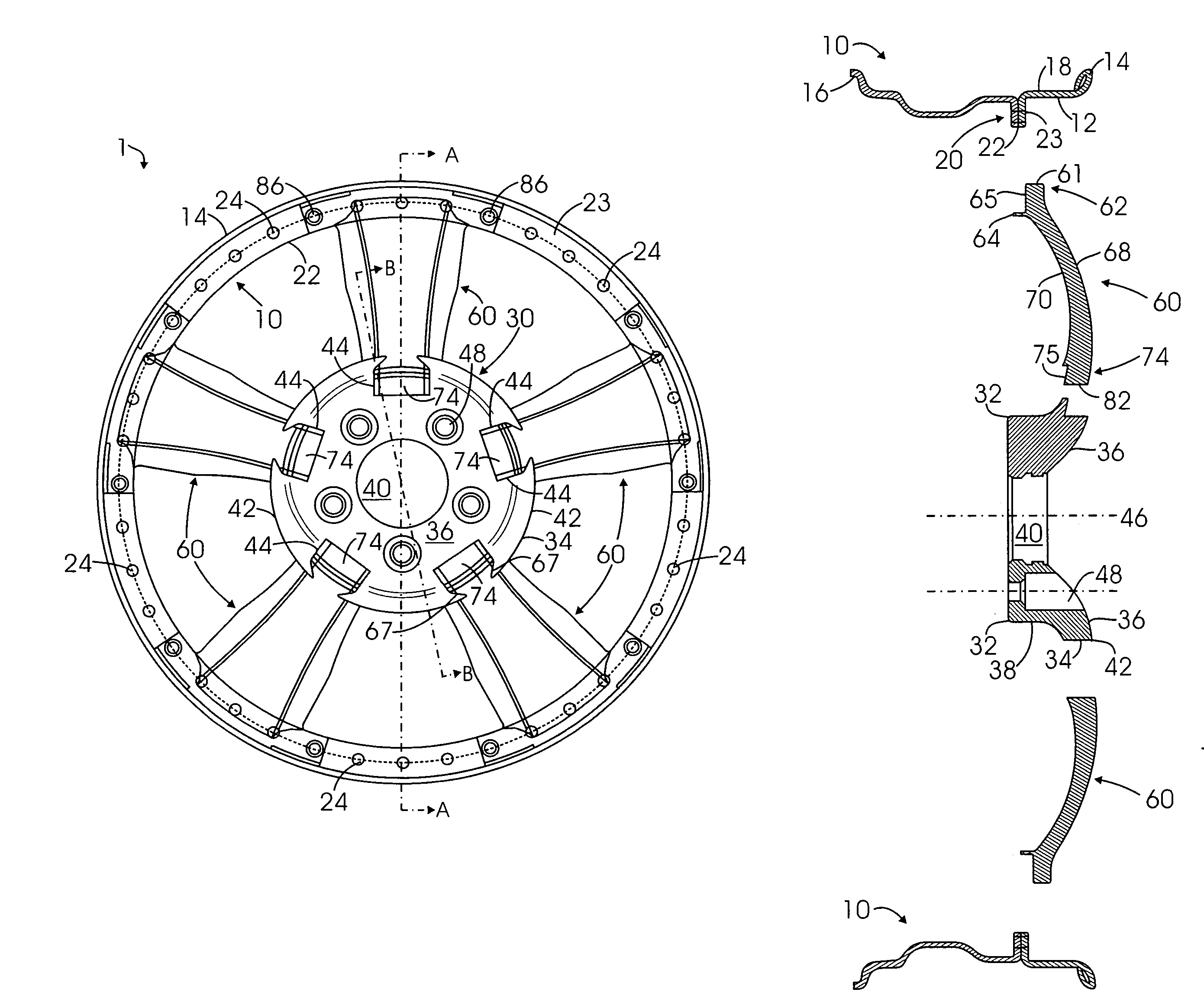
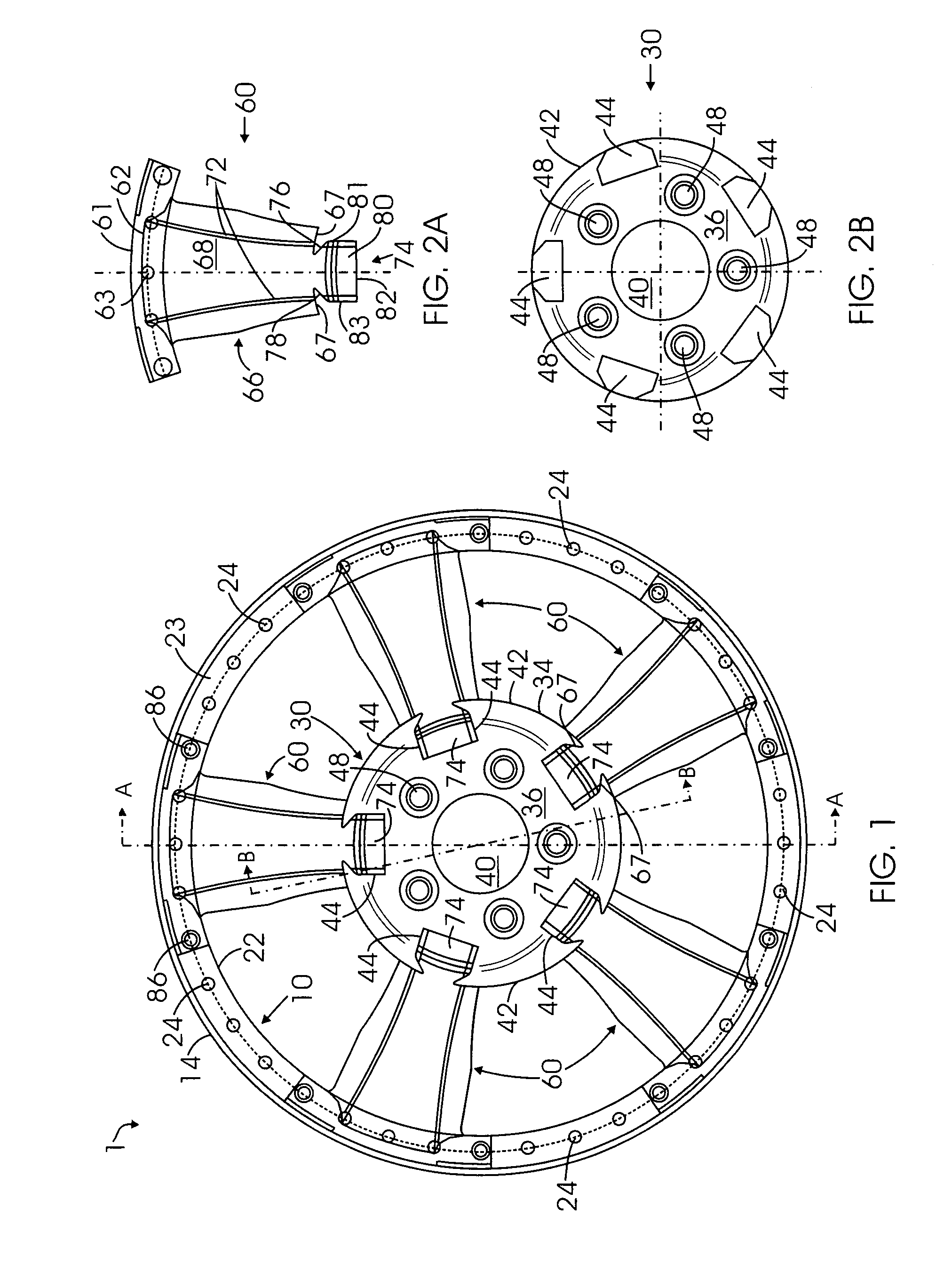
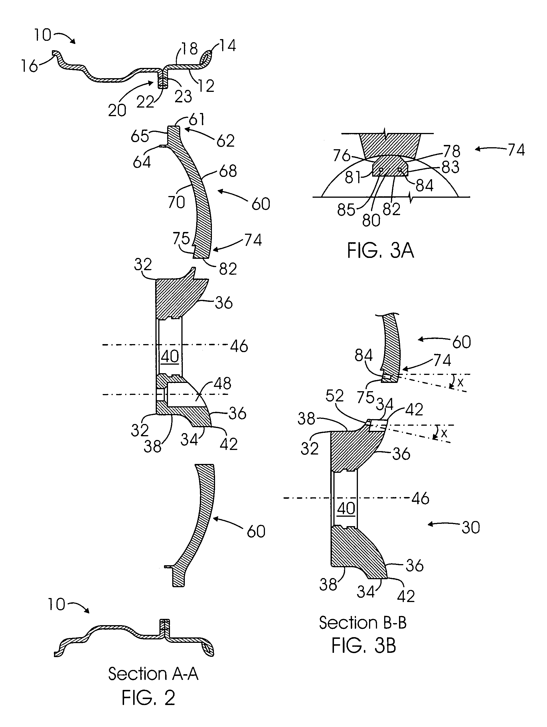
[0076]The embodiment 3 employs multiple identical spokes 360 to have the second ends 374, which are structurally different from the second spoke ends of the embodiments 1 and 2. As illustrated in FIGS. 7 to 9, a rectangular shoulder having an exterior elongated edge 382 acts as the second end 374 at its elongated side 373 and is connected to an exterior edge 367 of the spoke intermediate arcuate member 366, wherein a center of the elongated side 373 is aligned with a center of the exterior side 367 of the spoke intermediate member 366. Further referring to the illustration of FIG. 8, the second end 374 is connected, wherein its top rectangular surface is aligned with an arcuate outer surface 368 of the intermediate arcuate member 366. In addition, as illustrated in FIGS. 7 and 9, a first and second identical transverse bolt receiving hole 384 and 385 are symmetrically placed to penetrate through the second end 374.

[0077]Accordingly, for connection of the spoke second ends 374, which...

embodiment 4

[0079]Referring to FIGS. 10 through 12 illustrates that a second end 474 of each identical spoke 460, which is a flat rectangular shoulder, at its elongated side is connected to an exterior edge 467 of the intermediate arcuate member 466, wherein the length of the side matches the length of the edge. In addition, it further illustrates that first and second identical transverse bolt receiving holes 484 and 485 are symmetrically placed to penetrate through the spoke second end 474. Correspondingly, for matching each second end 474 of five spokes, five identical rectangular slots 444 are evenly placed in a circular pattern along the hub front exterior circumference 442 into the inside of the central hub 430, as particularly illustrated in FIGS. 11A and 12. Each rectangular slot 444 is transverse to a rotational axis 446 of the multi-piece wheel. In addition, first and second transverse bolt receiving holes 452 and 454 are arranged to penetrate through each rectangular slot from penetr...


PUM


Abstract

A multi-piece wheel, which is assembled with multiple pieces of pre-made structural members, including an outer wheel ring, a central hub and multiple spokes. The outer wheel ring is comprised of a circular wall for affixing a tire on its inner surface and connecting spokes on its outer surface. The spokes are the wheel intermediate members which at their respective first and second end are connected to the respective outer wheel ring and the central hub. The central hub is a circular structure including a central bore and front circular arcuate surface, wherein multiple pockets are placed on the front surface for connecting the spoke second ends to the central hub. Various structural variations of the central hub and spokes regarding their connection are also disclosed, which results in various embodiments of the present invention.

Description

BACKGROUND OF THE INVENTION[0001]1. Field of the Invention[0002]The present invention is related to a vehicle wheel, and more particularly to a multi-piece wheel, which is assembled with multiple pieces of pre-made structural members, including an outer wheel ring, a central hub and multiple spokes.[0003]2. Description of the Prior Art[0004]The following 13 patents and published patent applications are the closest prior art references which are related to the present invention.[0005]1. U.S. Pat. No. 5,938,291 issued to Donald Pankhurst et al. and assigned to GKN Sankey Limited on Aug. 17, 1999 for “Wheels” (hereafter the “Pankhurst Patent”);[0006]2. U.S. Pat. No. 6,517,168 issued to Garry Van Houten and assigned to Lacks Industries, Inc. on Feb. 11, 2003 for “Wheel Cover Having Interchangeable Turbine Pocket Inserts” (hereafter the “Van Houten Patent”);[0007]3. U.S. Published Patent Application No. 2004 / 0070259 issued to Ya-Wen Chuang on Apr. 15, 2004 for “Vehicle Wheel Assembly” (h...

Claims


Application Information

Patent Timeline
IPC IPC(8): B60B1/14
CPCB60B1/14
Inventor BAGDASARIAN, KEN L.
Owner BAGDASARIAN KEN L
Why Eureka
Try Eureka