
Method and apparatus for lubricating cylinder surface in large diesel engines

a technology for lubricating cylinders and diesel engines, applied in mechanical devices, engine lubrication, pressure lubrication with lubricating pump, etc., can solve the problems of difficult control of fed cylinder lubricating oil portion, difficult to establish in connection with conventional lubricating apparatuses, and inability to electronically achieve the effect of speed

Inactive Publication Date: 2010-03-23
HANS JENSEN LUBRICATORS
View PDF8 Cites 3 Cited by
  • Summary
  • Abstract
  • Description
  • Claims
  • Application Information

AI Technical Summary

Benefits of technology

[0022]The system according to the invention may be used for traditional lubrication and for e.g. SIP lubrication. The advantage of the invention and possibilities of saving would be just as attractive irrespective of the lubrication principle.
[0023]With the flow regulator it thus becomes possible to regulate the flow at a given number of lubricating points. The number of lubricating points with possibility of flow regulation depends on how flexible a user wants the regulation. With the system according to the invention, automatic shifting between lubricating points, where flow regulation is performed, is ensured.
[0024]The flow regulator applied may either be integrated in the lubrication apparatus or be mounted as a separate unit which is associated with existing or new lubricating apparatuses. The system according to the invention is thus advantageous in that it may be retrofitted in existing installations, irrespectively whether these prior art apparatuses are based on oil injection or pressure atomisation.
[0025]The flow regulator is controlled by the electronic control so that between the individual lubricating points and depending on actual need and load level, the lubricating oil is redirected to either the lubricating apparatus or to a reservoir for the lubricating oil. In principle, it may be said that regulation is performed by one or more of the lubricating points of the lubrication apparatus being “by-passed” in a lubricating stroke, and the lubrication thereby established over a period of time will enable a stepless adjustment of the portion or amount. This stepless quantitative adjusting occurs independently of the adjustability of the amount and may be combined with adjusting the amount by adjusting the stroke of the piston pumps.
[0026]With a flow regulation according to the invention, a programming of the electronic control may be performed. With a lubricating apparatus intended for feeding ten lubricating points, a 10% reduction may thus be effected by a lubricating point is bypassed in each succeeding cycle. After 10 cycles, all the lubricating points would have been bypassed. Irrespective of this bypassing, by using the system according to the invention in each cycle, lubrication of every cylinder is performed. This lubrication will, however, not necessarily occur at every lubrication point of the cylinder.
[0027]According to a further embodiment, the method according to the invention is peculiar in that the lubricating oil portion is redirected to the lubricating apparatus or to a lubricating oil reservoir. Hereby is achieved a very simple system as there will be no need of separate containers for receiving the redirected lubricating oil portion.

Problems solved by technology

Driving the lubricating apparatuses synchronously with the engine speed is electronically feasible, but extensive and costly.
Changing the fed cylinder lubricating oil portion is, however, more difficult to control.
This has been used for point lubrication, but it is difficult to establish in connection with conventional lubricating apparatuses.

Method used


Image

  • Method and apparatus for lubricating cylinder surface in large diesel engines
  • Method and apparatus for lubricating cylinder surface in large diesel engines
  • Method and apparatus for lubricating cylinder surface in large diesel engines

Examples


Embodiment Construction

[0052]In the Figures of the drawing, identical or corresponding elements will be provided the same designations. No detailed explanation of such details will thus be given in connection with each Figure.

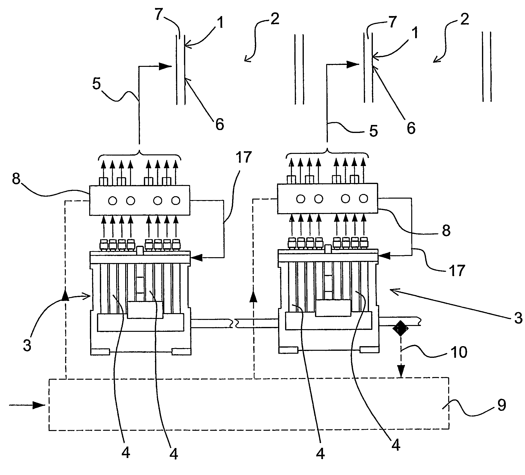
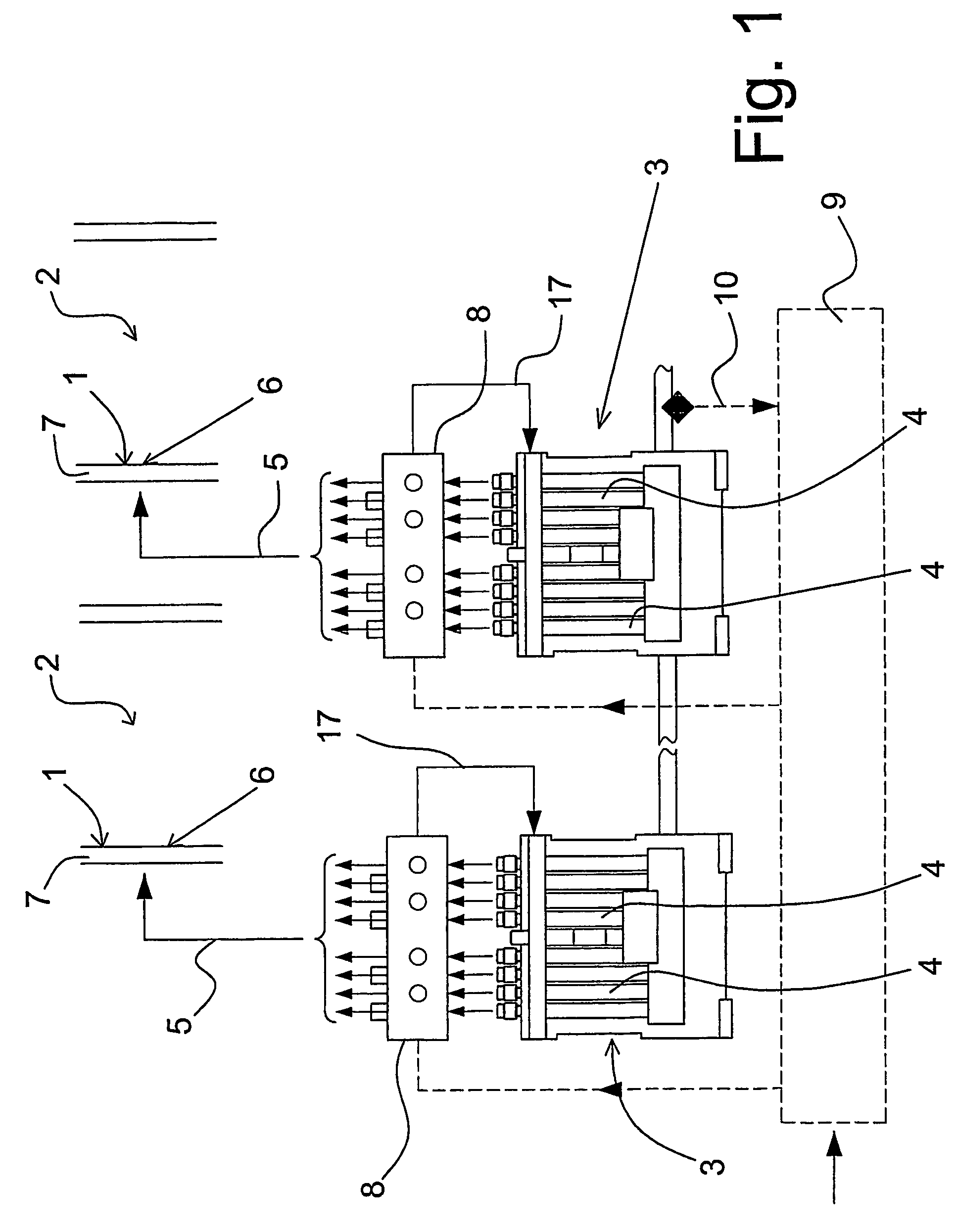
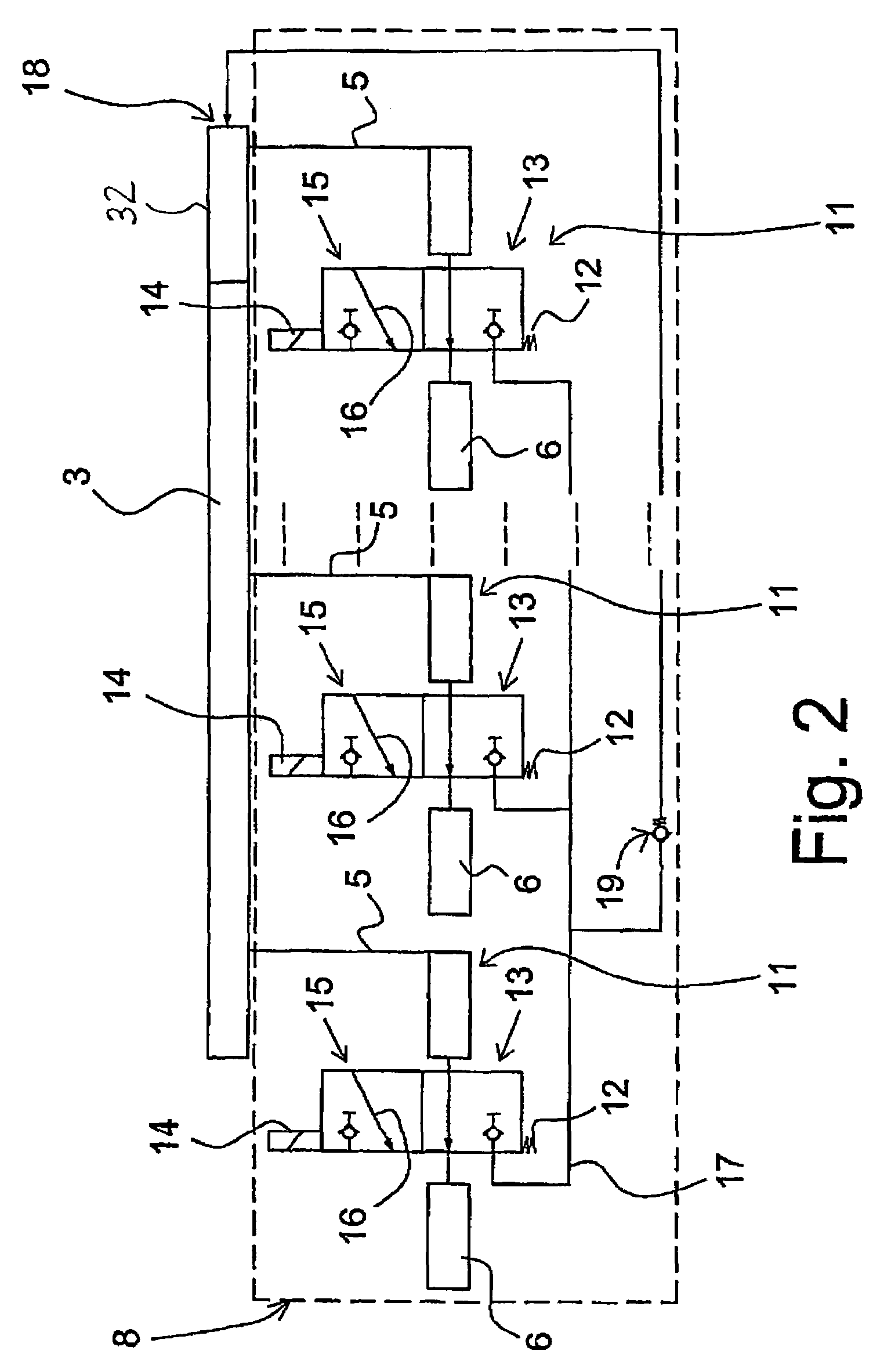
[0053]FIG. 1 shows an installation for lubricating cylinder faces 1 in cylinders 2 in large diesel engines. The shown installation includes two lubricating apparatuses 3 that each has a series of piston pumps indicated by 4. Via connecting lines 5 (of which only one is illustrated for each lubricating apparatus), each of the piston pumps are connected with a lubricating point 6 disposed in the cylinder wall 7 for lubricating the cylinder surface 1 of the cylinder wall. The installation furthermore includes a flow regulator 8 which will be explained in more detail with reference to FIG. 2.

[0054]Furthermore, the installation includes an electronic control unit 9 which is connected with the flow regulators 8 and the lubricating apparatuses 3. As indicated by 10, the flow regulator can r...


PUM


Abstract

There is described a method and an installation for lubricating cylinder surfaces 6 in large diesel engines. The installation includes a lubricating apparatus 3 with a number of piston pumps 4 which via connecting lines 5 are connected with lubricating points 6 in the cylinder walls 7. In order to enable electronically controlled regulation of the lubricating oil portion, there is provided an electronic control unit 9 which is connected with a flow regulator 8. The flow regulator includes redirecting valves 12 which are inserted in connecting lines 5 between the lubricating apparatus 3 and the lubricating points 6.

Description

BACKGROUND OF THE INVENTION.[0001]This application claims the benefit of Danish Application No. PA 2004 03035filed Jun. 30, 2004and PCT / DK2005 / 000445filed Jun. 30, 2005, which are hereby incorporated by reference in their entirety.[0002]The present invention concerns a lubricating system that includes a method and an installation for lubricating the cylinder faces in large diesel engines, particularly marine engines, including at least one lubricating apparatus with a number of piston pumps which via connecting lines are connected with and feed various lubricating points disposed in the walls of the cylinders.[0003]The lubricating apparatuses are traditionally designed as pumping units which are mounted in close association with respective cylinders, and which are connected with a feeding reservoir for lubricating oil and with lubricating points in the form of oil injection nozzles at different points on the cylinder wall. Each pump unit includes a plurality of piston pumps that fee...

Claims


Application Information

Patent Timeline
Patent Type & Authority Patents(United States)
IPC IPC(8): F01M1/08F01M1/14F01M1/16
CPCF01M1/14F01M1/16F01M2001/083F01M3/04
Inventor AAMAND, JAN
Owner HANS JENSEN LUBRICATORS
Learn More