Dynamic network protection
- Summary
- Abstract
- Description
- Claims
- Application Information
AI Technical Summary
Benefits of technology
Problems solved by technology
Method used
Image
Examples
Embodiment Construction
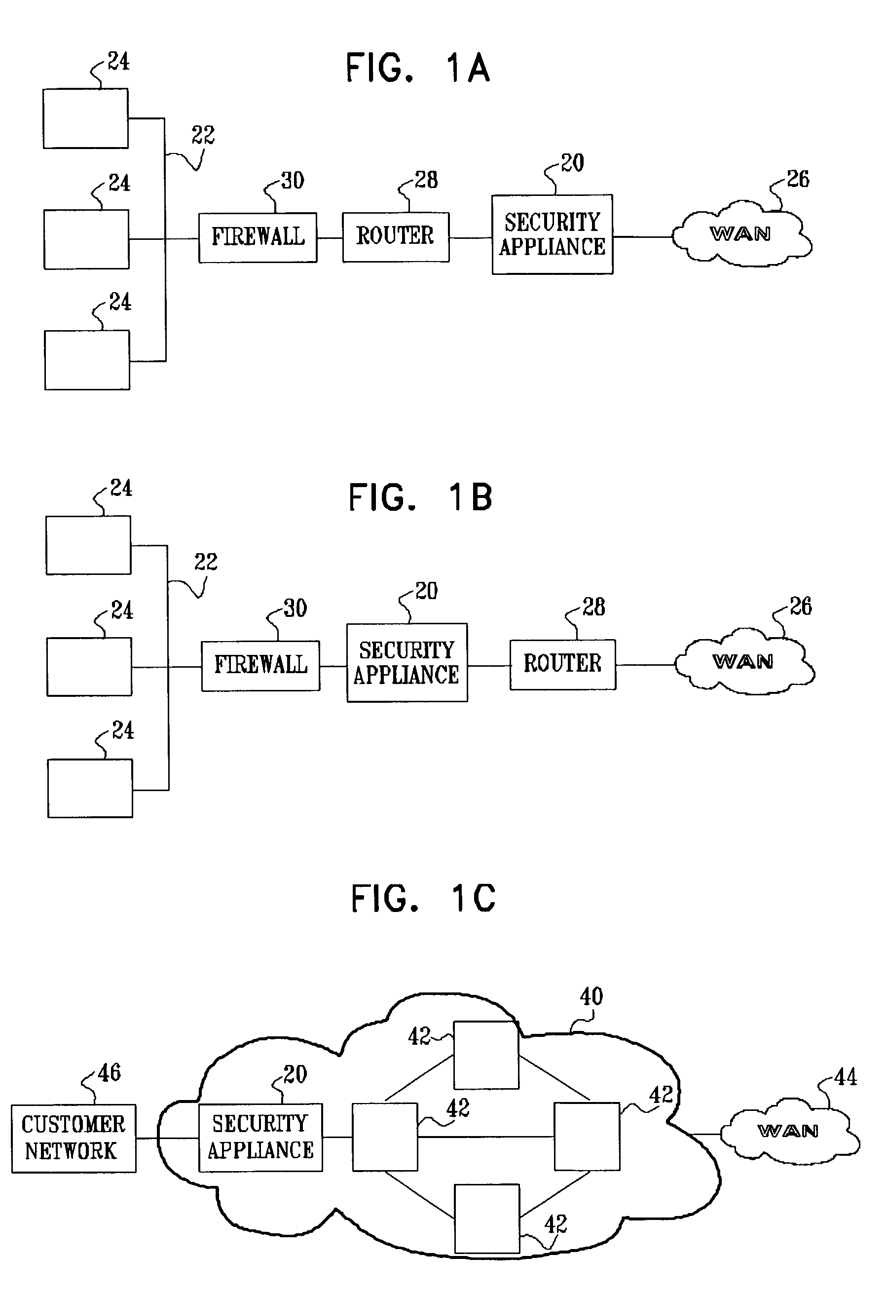
[0117]FIGS. 1A and 1B are block diagrams that schematically illustrate a network security system 20 deployed at the periphery of a protected network 22, in accordance with embodiments of the present invention. Protected network 22 comprises various network elements 24, such as servers, clients, routers, switches, and bridges, connected by one or more local-area networks (LANs). Protected network 22 may be a private network, for example, such as an enterprise or campus network. The protected network is connected to a wide-area network (WAN) 26, such as the Internet, through at least one router 28. At least one firewall 30 is typically deployed at the periphery of protected network 22, between the protected network and router 28. Security system 20 may be deployed between router 28 and WAN 26, as shown in FIG. 1A, or between firewall 30 and router 28, as shown in FIG. 1B. Alternatively, system 20 may be deployed in front of a group of one or more network elements 24, such as in front ...
PUM
 Abstract
Description
Claims
Application Information
 - R&D
- Intellectual Property
- Life Sciences
- Materials
- Tech Scout
- Unparalleled Data Quality
- Higher Quality Content
- 60% Fewer Hallucinations
Browse by: Latest US Patents, China's latest patents, Technical Efficacy Thesaurus, Application Domain, Technology Topic, Popular Technical Reports.
© 2025 PatSnap. All rights reserved.Legal|Privacy policy|Modern Slavery Act Transparency Statement|Sitemap|About US| Contact US: help@patsnap.com


