Liquid-lens assembly

a technology of liquid lens and assembly, which is applied in the direction of printers, instruments, camera focusing arrangement, etc., can solve the problems of difficult to mount the controllable focus lens to a mobile terminal, other problems than the above-mentioned problems, and achieve the effect of simple and reliable structur

Inactive Publication Date: 2010-03-16
SAMSUNG ELECTRO MECHANICS CO LTD
View PDF8 Cites 4 Cited by
  • Summary
  • Abstract
  • Description
  • Claims
  • Application Information

AI Technical Summary

Benefits of technology

[0019]Accordingly, the present invention has been made keeping in mind the above problems occurring in the prior art, and an object of the present invention is to provide a liquid-lens assembly, which has a simpler and more reliable structure, by which current can be applied to a liquid-lens module.
[0020]Another object of the present invention is to provide a liquid-lens assembly, the shape of which is changed to allow the focus of the liquid-lens assembly to be easily controlled.

Problems solved by technology

Further, since additional parts required for driving the lens, such as a motor, must be mounted, it is difficult to realize miniaturization of the camera.
Further, when the controllable focus lens is driven in the mechanical method, as in the prior art, problems other than the above-mentioned problems occur.
That is, since an electric motor installed to drive the controllable focus lens consumes a considerable amount of battery power, it is technically difficult to mount the controllable focus lens to a mobile terminal.
Moreover, in order to control the focus of the lens using the conventional mechanical method, a certain amount of time is required.
Further, since the electric wire is provided outside the liquid-lens module, the appearance thereof is untidy.
Furthermore, the method of applying current through the electric wire is problematic in that the reliability of the power supply is low.

Method used


Image

  • Liquid-lens assembly
  • Liquid-lens assembly
  • Liquid-lens assembly

Examples


Embodiment Construction

[0032]Hereinafter, the present invention will be described in detail with reference to the accompanying drawings.

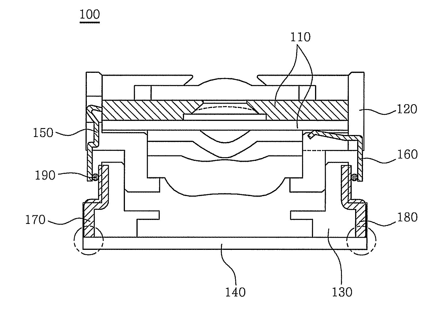
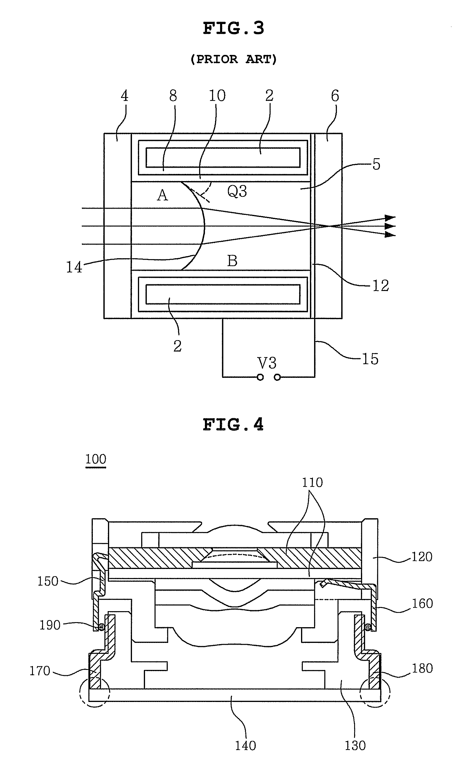
[0033]FIG. 4 shows a liquid-lens assembly, according to an embodiment of the present invention, FIG. 5 shows only a barrel, out of the components of the liquid-lens assembly, according to the present invention, FIGS. 6A and 6B show the state where a liquid-lens module is installed in the barrel, FIGS. 7A and 7B show a housing of the liquid-lens assembly, according to the present invention, and FIGS. 8A and 8B show a housing of a liquid-lens assembly according to another embodiment of the present invention.

[0034]The liquid-lens assembly 100 according to the present invention includes a liquid-lens module 110, a barrel 120, and a housing 130. The liquid-lens module 110 uses an electrowetting method, and applies current through two electrodes. The barrel 120 supports the liquid-lens module 110. The housing 130 is coupled to the barrel 120 via a coupling means 190, and is pro...


PUM


Abstract

Disclosed herein is a liquid-lens assembly using an electrowetting method. The liquid-lens assembly includes a liquid-lens module, a barrel supporting the liquid-lens module, and a housing coupled to the barrel and having an image sensor. Electrodes are provided on the barrel and the housing, so that current is applied to the liquid-lens module through the electrodes.

Description

CROSS REFERENCE TO RELATED APPLICATION(S)[0001]This application claims the benefit of Korean Patent Application No. 10-2006-0075747, filed on Aug. 10, 2006, entitled “liquid-lens assembly”, which is hereby incorporated by reference in its entirety into this application.BACKGROUND OF THE INVENTION[0002]1. Field of the Invention[0003]The present invention relates generally to a liquid-lens assembly using an electrowetting phenomenon and, more particularly, to a liquid-lens assembly, in which the structure for applying current to a liquid-lens module is simplified.[0004]2. Description of the Related Art[0005]Currently, a camera having a controllable focus function is applied to various kinds of portable multimedia equipment, including a mobile communication terminal, a small digital camera, an automatic camera, etc. As technology is gradually developed, efforts to integrate various devices, including a camera, into a single piece of mobile equipment and miniaturize the equipment have b...

Claims


Application Information

Patent Timeline
Patent Type & Authority Patents(United States)
IPC IPC(8): G03B3/00
CPCG03B13/32G02B1/06G02B3/14G02B7/028G02B7/04G02B26/005G02B27/646G03B30/00
Inventor JUNG, MOON SIK
Owner SAMSUNG ELECTRO MECHANICS CO LTD
Why Eureka
Try Eureka