Balancing device

a balancing device and core assembly technology, applied in the direction of instruments, structural/machine measurement, engine fuction, etc., can solve the problems of increasing the mass to be accelerated, taking a great deal of time to fix the core assembly, and achieving a simple and reliable structure.

Active Publication Date: 2019-09-10
CHRISTOPH BOHMER BETRIEBSVERPACHTUNG GMBH
View PDF7 Cites 0 Cited by
  • Summary
  • Abstract
  • Description
  • Claims
  • Application Information

AI Technical Summary

Benefits of technology

[0010]It is therefore the object of the present invention to provide a balancing device which has a simpler and more reliable structure.
[0014]The decoupling plate itself, made in one part, remains substantially stable here, and this has a positive effect in the event of incorrect fitting of the balancing device because the stability of the decoupling plate is substantially maintained, and so, for example, overloading is successfully counteracted as with the spring elements known from the prior art.
[0026]If the hydraulic cylinders are arranged on and fastened to the inner plate section, it is possible for all of the other masses provided on the balancing device to remain on the outer plate section fixed stationarily to the balancing device so that the rotation movement of the rotation element can take place with clearly less additional mass because only one rotation of the inner plate section together with the hydraulic cylinders can take place. The risk of falsifying the measurements taken can thus be clearly reduced.
[0028]One improvement of the automatability of the method for balancing core assemblies and rotation elements makes provision to provide a number of pneumatic cylinders on the outer fixed plate section in order to position the hydraulic cylinders and / or the lever elements on the rotation element to be fastened after inserting the rotation element into the central receiver, and then to move the pneumatic cylinders fastened stationarily to the outer plate section back in the central receiver after fixing the rotation element by means of the lever elements. It is thus possible to provide automatic positioning of the lever elements on the rotation element that is to be fastened and to prevent further masses that have a negative impact upon the vibration of the rotation element from affecting the balancing process, for example by means of the pneumatic cylinders.

Problems solved by technology

However, it is a disadvantage of this type of solution that in each case it takes a great deal of time to fix the core assembly in place, and this considerably extends the cycle times of the balancing device.
However, this form of support structure is very cumbersome and solid, and so increases the masses to be accelerated in the balancing process, and this may lead to falsification of the balancing result.
However, a disadvantage of this design of decoupling element is that the core assembly must be fastened to the structure by hydraulic cylinders fastened to the base element.
However, it is very complex to produce these windows reproducibly.
On the other hand, if the balancing device is not fitted correctly, for example if the core assembly is not inserted, there is the risk that, due to the radial forces exerted by the hydraulic cylinders upon the axial fixing of the core assembly and the associated forces exerted upon the decoupling element, the hydraulic cylinders as well as the window elements will move into the receiver so that the spring elements formed between the base structure and the support structure will ultimately break.
As a consequence, the entire decoupling element made in one part must be replaced because the spring elements provided between the base element and the supporting element cannot be replaced.

Method used


Image

  • Balancing device
  • Balancing device
  • Balancing device

Examples


Embodiment Construction

)

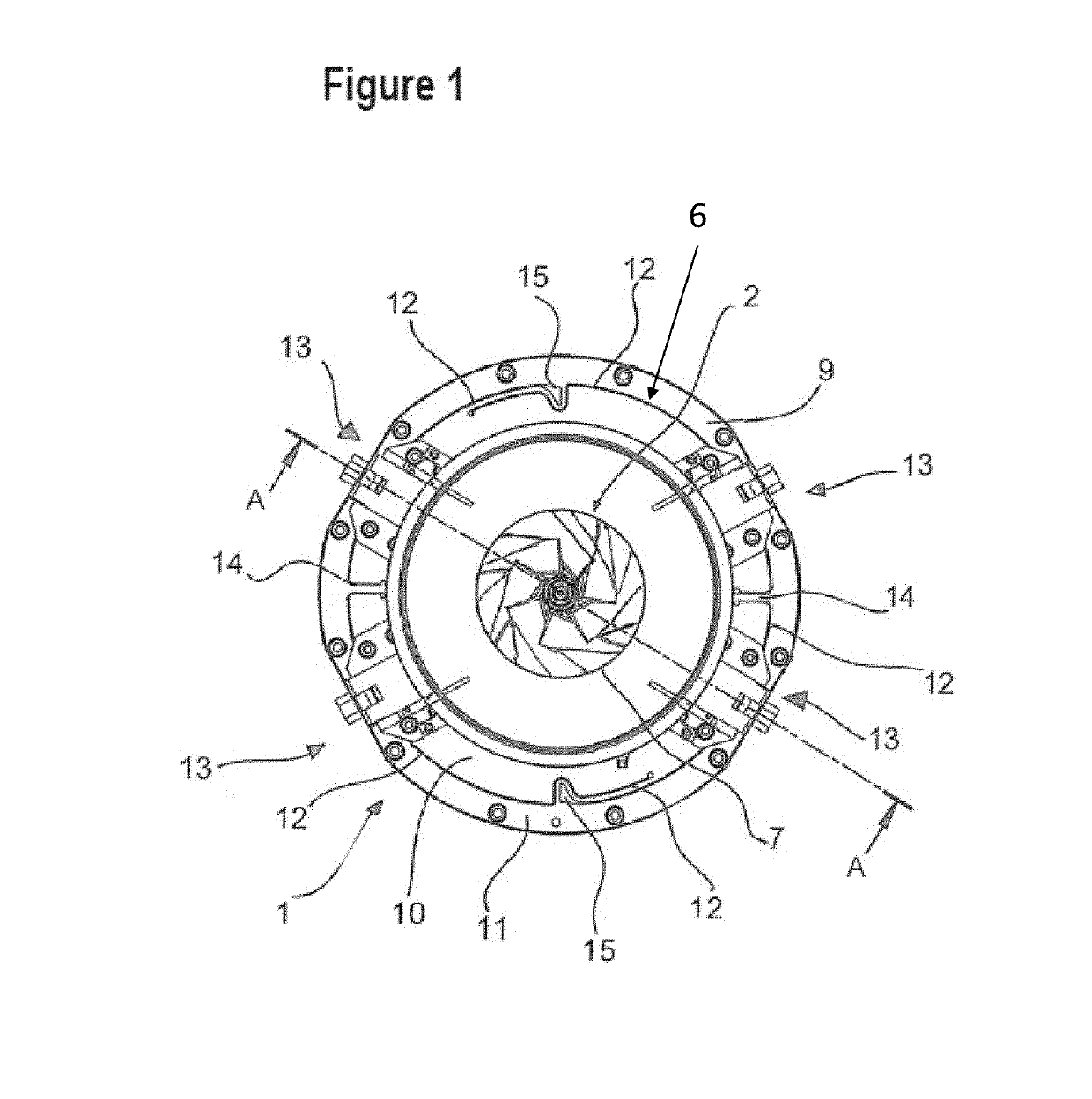
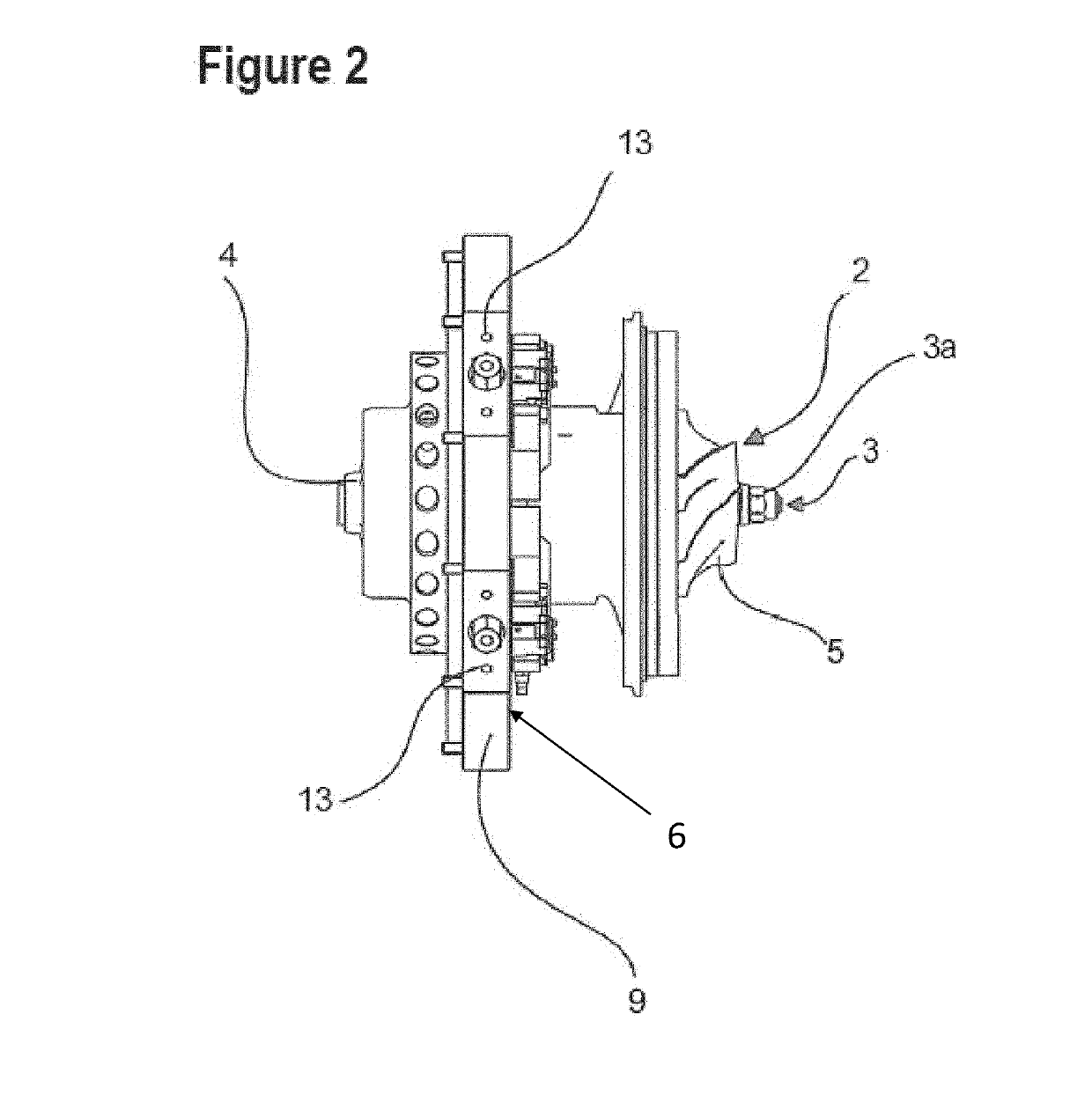
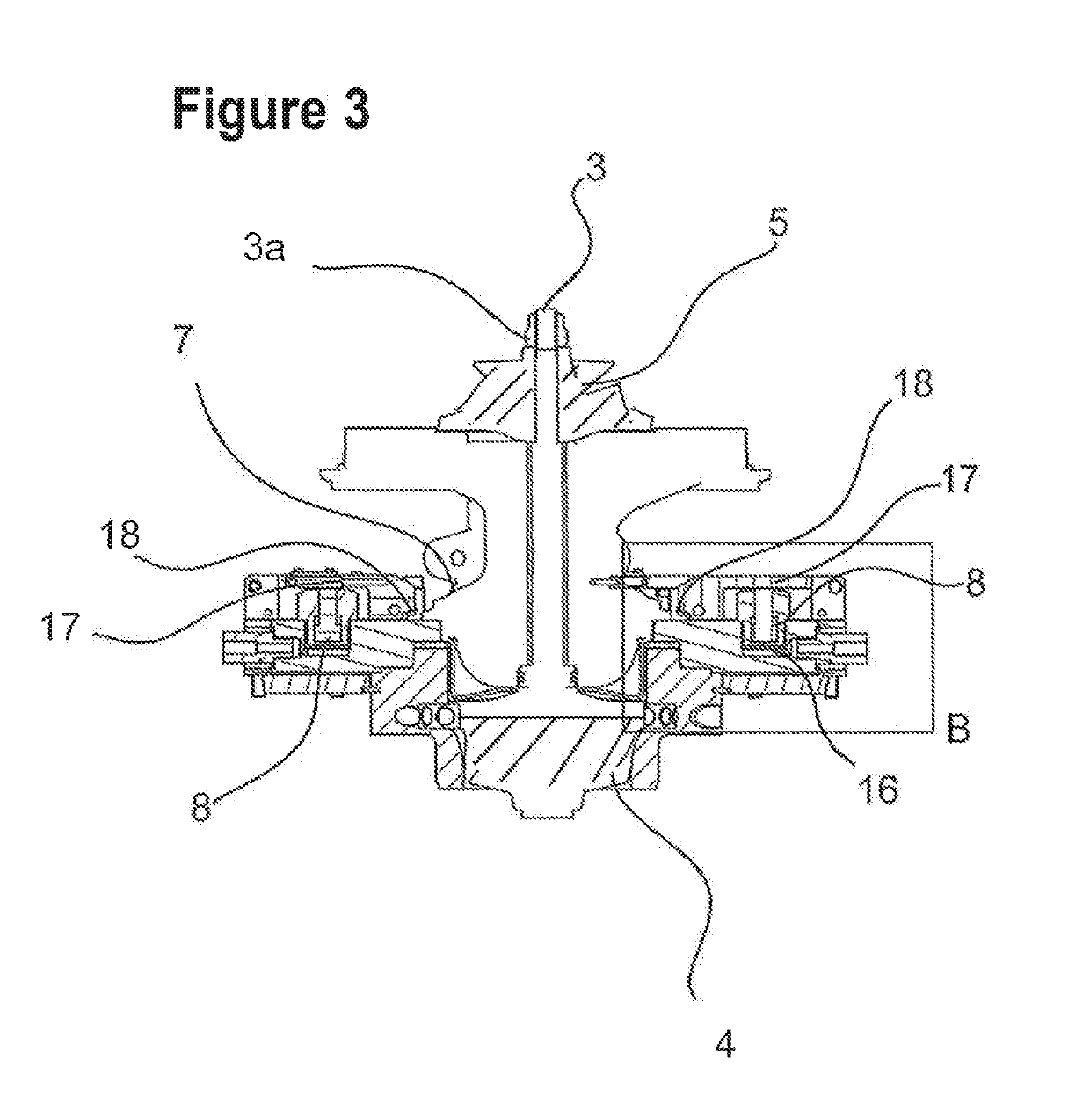
[0036]FIG. 1 shows a balancing device 1 for a core assembly 2 of a turbocharger. The core assembly 2 comprises a shaft 3 to each of the ends of which a turbine wheel 4 and a compressor wheel 5 of the turbocharger are fastened and fixed in place by means of a shaft nut 3a.

[0037]The balancing device 1 is provided with a base body 6 which has a centrally positioned receiver 7 in order to insert the core assembly 2 into the receiver 7 and to keep the rotation element 3, 4, 5 turning about its axis of rotation by means of bearings (not detailed). Provided on the base body 6 are a number of hydraulic cylinders 8 arranged around the receiver 7, by means of which the core assembly 2 is fastened in the central receiver 7.

[0038]The base body 6 has a circular decoupling plate 9 which comprises an inner plate section 10 and an outer plate section 11 disposed stationarily in the balancing device 1, elastically connected to the inner plate section 10 and surrounding the inner plate section 10.

[...


PUM


Abstract

A balancing device for turbochargers comprises a base body having a centrally disposed receiver. A rotation element to be balanced can be axially inserted to hold the rotation element in the receiver such as to turn about its axis of rotation. A number of hydraulic cylinders are arranged around the central receiver on the base body for fixing a core assembly of the turbocharger in the central receiver. The base body is in the form of a decoupling plate having an inner plate section and a stationarily positioned outer plate section elastically connected to the inner plate section and surrounding the inner plate section. The decoupling plate has a number of peripheral slots resiliently decoupling the inner plate section from the outer plate section such that a number of separate holding sections are formed on the de-coupling plate.

Description

CROSS-REFERENCE TO RELATED APPLICATIONS AND CLAIM TO PRIORITY[0001]This application is related to application number 17 158 764.5, filed Mar. 1, 2017, with the European Patent Office, the disclosure of which is incorporated herein by reference and to which priority is claimed.FIELD OF THE INVENTION[0002]The present invention relates to a balancing device, in particular for turbochargers, comprising a base body which has a centrally disposed receiver into which a rotation element to be balanced, in particular a core assembly of a turbocharger, can be axially inserted in order to hold the rotation element in the receiver such as to turn about its axis of rotation, a number of hydraulic cylinders arranged around the receiver being provided on the base body, by means of which hydraulic cylinders the rotation element is fixed or can be fixed in the central receiver.BACKGROUND OF THE INVENTION[0003]Balancing devices of the type specified above for dynamically measuring imbalances on a rot...

Claims


Application Information

Patent Timeline
Patent Type & Authority Patents(United States)
IPC IPC(8): F04D29/66G01M1/04F04D25/02F01D25/28F01D5/02
CPCF04D29/662F04D25/024F04D29/668G01M1/04F05D2260/15F01D5/027F01D25/285F05D2220/40G01M1/02G01M1/16F01D25/18B26F3/004
Inventor BOEHMER, CHRISTOPHBOEHMER, STEFAN
Owner CHRISTOPH BOHMER BETRIEBSVERPACHTUNG GMBH
Why Eureka
Try Eureka