
Coupled waveguide-surface plasmon resonance biosensor

a plasmon resonance and coupled waveguide technology, applied in the field of biosensors, can solve the problems of inability to obtain dynamics information of real-time interaction, inability to detect plasmon resonance, etc., and achieve the effect of improving resolution and enhancing sensitivity

Active Publication Date: 2010-03-16
IND TECH RES INST
View PDF4 Cites 5 Cited by
  • Summary
  • Abstract
  • Description
  • Claims
  • Application Information

AI Technical Summary

Benefits of technology

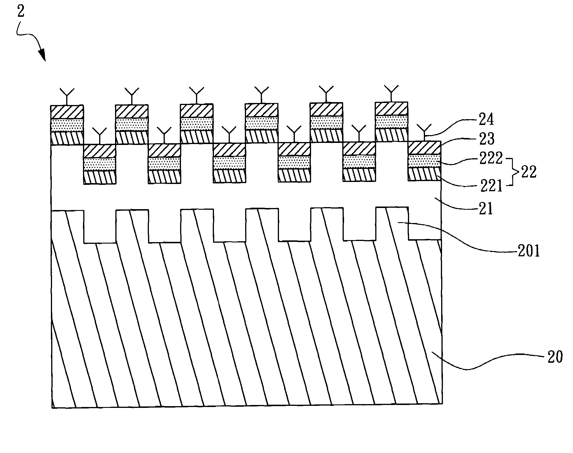
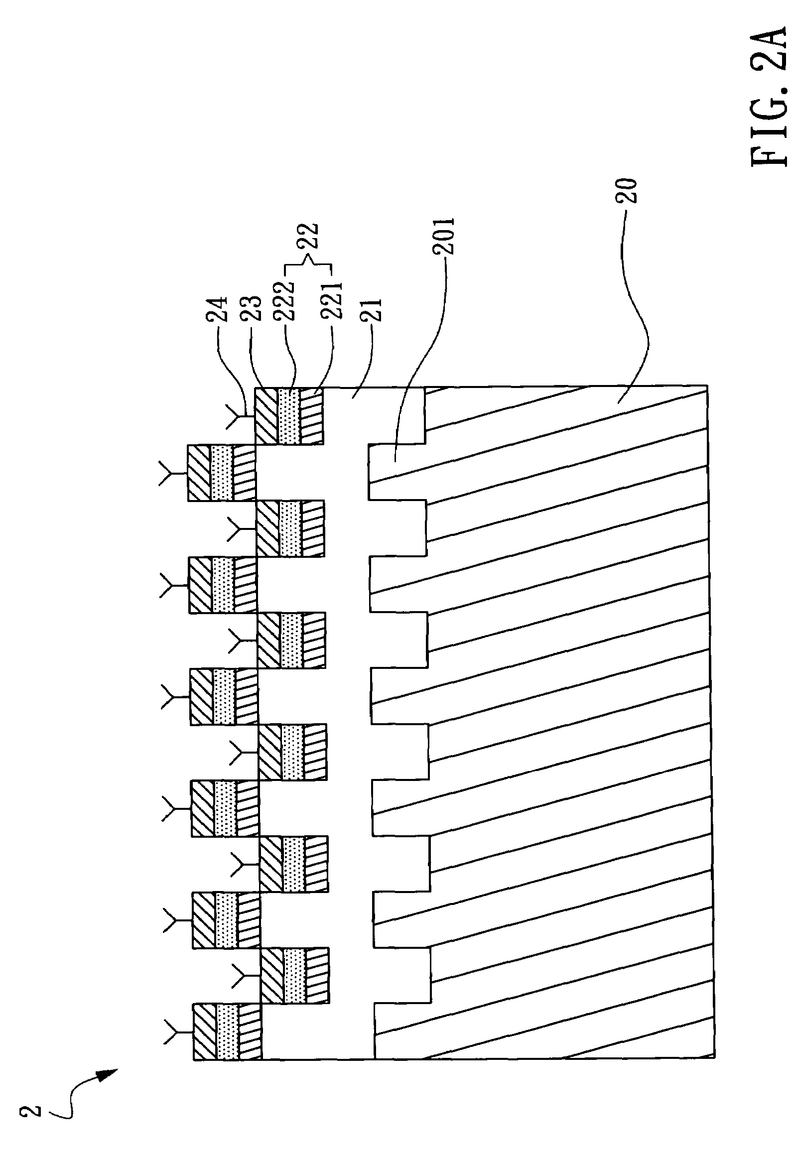
The present invention provides a coupled waveguide-surface plasmon resonance biosensor that can detect bio-molecular interactions in real-time without labeling. The biosensor uses a grating layer, a waveguide layer, a plasmon resonance layer, and a ligand layer. The plasmon resonance layer is made of a metal film or a metal particle layer, which is formed on the waveguide layer or the grating layer. The biosensor can measure the resonance peak caused by plasmon resonance waves, which are optically excited on the metal surface. The biosensor has improved sensitivity and resolution by using a reduced reflection resonance peak. The invention also provides a self-assembled monolayer for the biosensor. The technical effects of the invention include improved sensitivity, resolution, and real-time detection of bio-molecular interactions.

Problems solved by technology

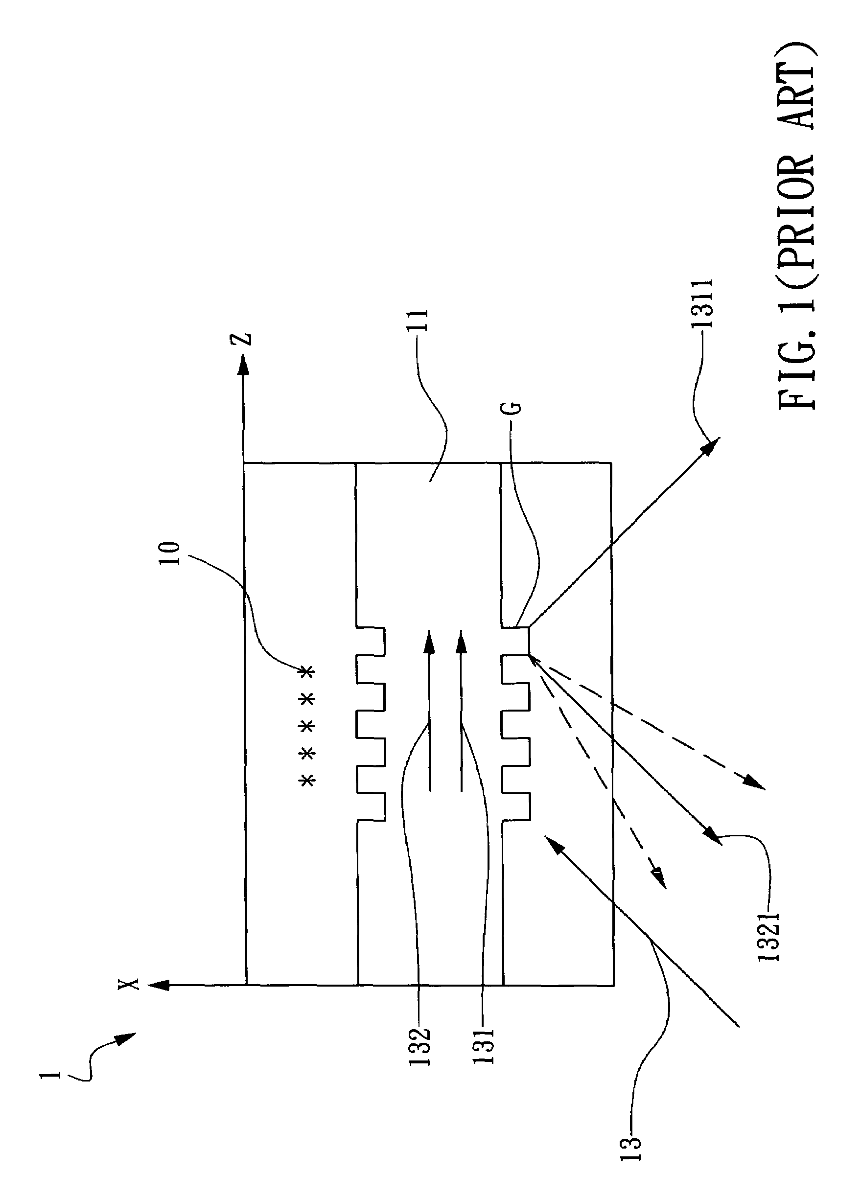
In fluorescence detection, problems related to complicated fluorescence tags, difficulty in molecule tags, inevitable fluorescence decay and unavailability in dynamics information of real-time interaction occur.
However, the reflectance spectrum exhibits a wide FWHM (full width at half magnitude) leading to a poor wavelength resolution so that detection in physiology concentration is unavailable.

Method used


Image

  • Coupled waveguide-surface plasmon resonance biosensor
  • Coupled waveguide-surface plasmon resonance biosensor
  • Coupled waveguide-surface plasmon resonance biosensor

Examples


Embodiment Construction

[0038]The present invention providing a coupled waveguide-surface plasmon resonance biosensor can be exemplified by the preferred embodiments as described hereinafter.

[0039]Coupled waveguide-surface plasmon resonance indicates that surface plasma are excited only at a small range of wavelength or by monochromatic light at a specific incident angles. The wavelength and the angle are referred to as the coupled waveguide-surface plasmon resonance wavelength and the coupled waveguide-surface plasmon resonance angle, respectively. When the coupled waveguide-surface plasmon resonance structure is disturbed by, for example, the minimal change of reflection index or thickness caused by bio-molecular absorption on the surface, the wave vector of the coupled surface plasma changes to cause variation of the resonance wavelength or the resonance angle. Therefore, bio-molecular interaction can be detected dynamically without labeling. Such a coupled waveguide-surface plasmon resonance structure ...


PUM

PropertyMeasurementUnit
thicknessaaaaaaaaaa
diameteraaaaaaaaaa
depthaaaaaaaaaa

Abstract

The present invention discloses a coupled waveguide-surface plasmon resonance biosensor, comprising: a grating layer formed of a transparent material, the grating layer comprising a first periodic grating structure; a waveguide layer formed on the first periodic grating structure, the refractive index of the waveguide layer being larger than the refractive index of the grating layer; a plasmon resonance layer formed on the waveguide layer, capable of being optically excited to cause a plasmon resonance wave; and a ligand layer formed on the plasmon resonance layer; capable of being bound to react with receptors of a sample to be tested.

Description

BACKGROUND OF THE INVENTION[0001]1. Field of the Invention[0002]The present invention generally relates to a biosensor and, more particularly, to a coupled waveguide-surface plasmon resonance biosensor using a grating and a metal material without labeling so as to detect bio-molecular interaction in real time.[0003]2. Description of the Prior Art[0004]In bio-molecular interaction analysis (BIA), bio-chips have attracted tremendous attention from genomics into proteomics. Bio-chips are used to detect genetic performance and bio-molecular messages. The current detection is done mainly by fluorescence detection. In fluorescence detection, problems related to complicated fluorescence tags, difficulty in molecule tags, inevitable fluorescence decay and unavailability in dynamics information of real-time interaction occur. Therefore, a label-free detecting method is required. In 1902, R. W. Wood discovered exceptional reflection gratings. Afterwards, theoretical reports and experiments on...

Claims


Application Information

Patent Timeline
Patent Type & Authority Patents(United States)
IPC IPC(8): G01N21/55
CPCG01N21/7703G01N21/7743
Inventor CHEN, SHEAN-JENMAO, YEN-CHIEHYIH, JENG-NANCHIEN, FAN-CHINGLIN, CHUN-YUCHU, YI-MINGCHEN, LAI-SHENGWANG, WEI-HANWU, CHAO-CHILIN, YEN-CHUN
Owner IND TECH RES INST
Learn More