
Integrated lime kiln process

a technology of integrated lime kiln and process, which is applied in the direction of chemical/physical processes, magnesium compounds, sulfur preparation/purification, etc., can solve the problems of reducing the efficiency of the kiln, and requiring the use of fossil fuels, so as to achieve the effect of optimizing the pollutan

Active Publication Date: 2010-03-16
GRAYMONT PA INC
View PDF11 Cites 4 Cited by
  • Summary
  • Abstract
  • Description
  • Claims
  • Application Information

AI Technical Summary

Benefits of technology

"The present invention provides an improved technique for recovering waste heat from a kiln and using the heat energy to generate power while concurrently optimizing pollutant dry scrubbing. This allows for the use of previously undesirable fuels for firing the kiln. The invention also provides an integrated kiln process that includes a waste heat recovery circuit, a boiler, and a steam turbine, which function as a heat exchanger and scrubbing the discharge gas. Additionally, the invention provides a method for dry scrubbing gas generated from the combustion of high sulphur based fuel in a kiln process. The technical effects of the invention include improved energy recovery and reduced acidic attack on heat exchange surfaces."

Problems solved by technology

The required use of fossil fuels can present pollution concerns and, depending upon the type of fuel used, may require a further unit operation, such as flue gas desulfurization, to satiate the problem.
Typically, it is dumped to the surrounding environment and wasted.
This is less energy-efficient, represents a sub-optimum economic condition, and contributes to long-term environmental concerns such as the production of green house gases.
When burning fossil fuels containing sulfur, corrosive acidic formations will occur on boiler surfaces that are below acid dew temperature.

Method used


Image

  • Integrated lime kiln process
  • Integrated lime kiln process
  • Integrated lime kiln process

Examples


Embodiment Construction

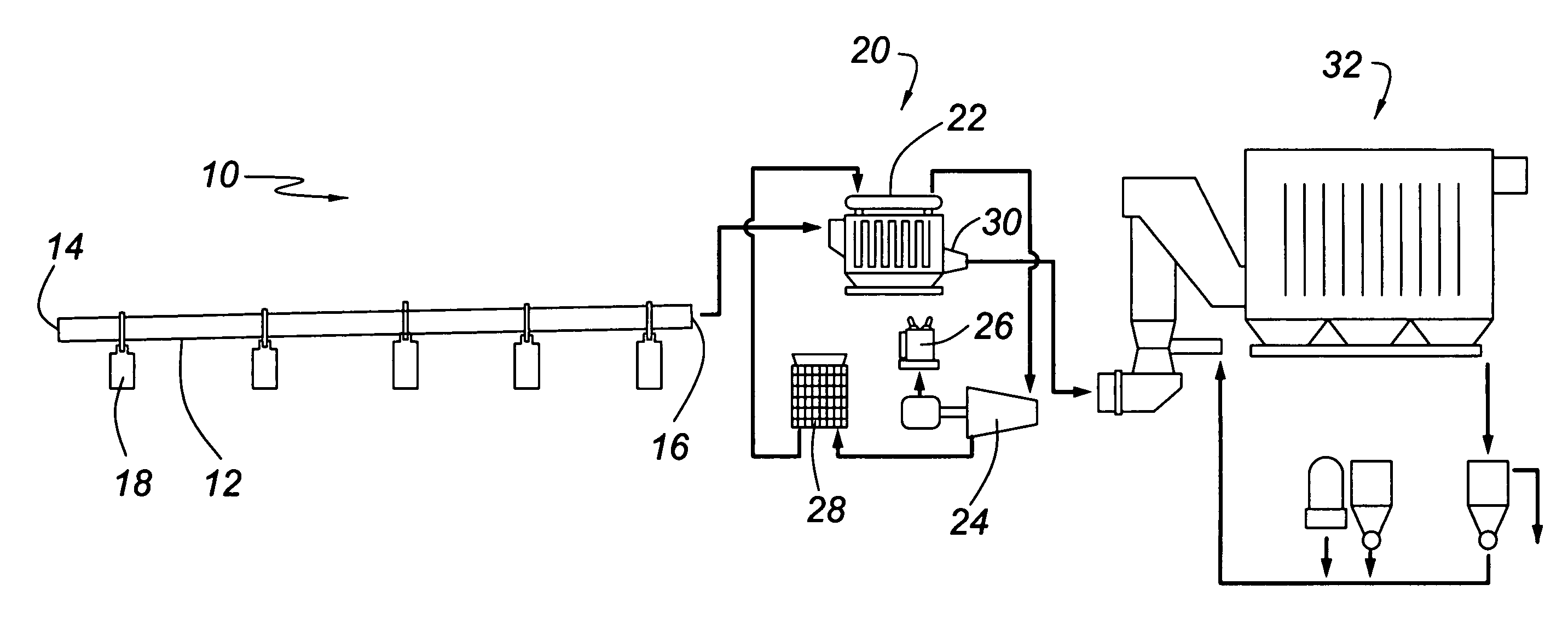
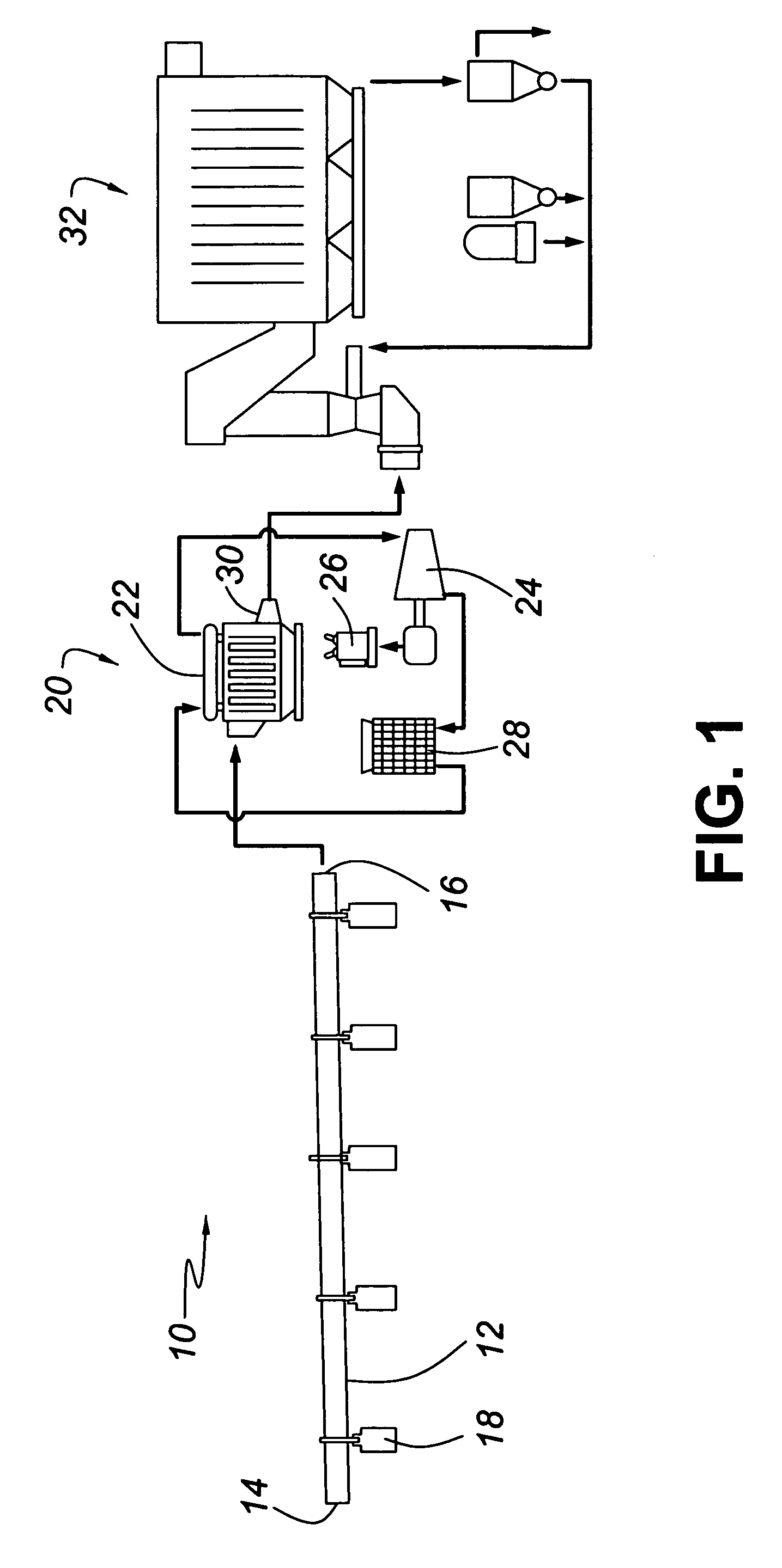
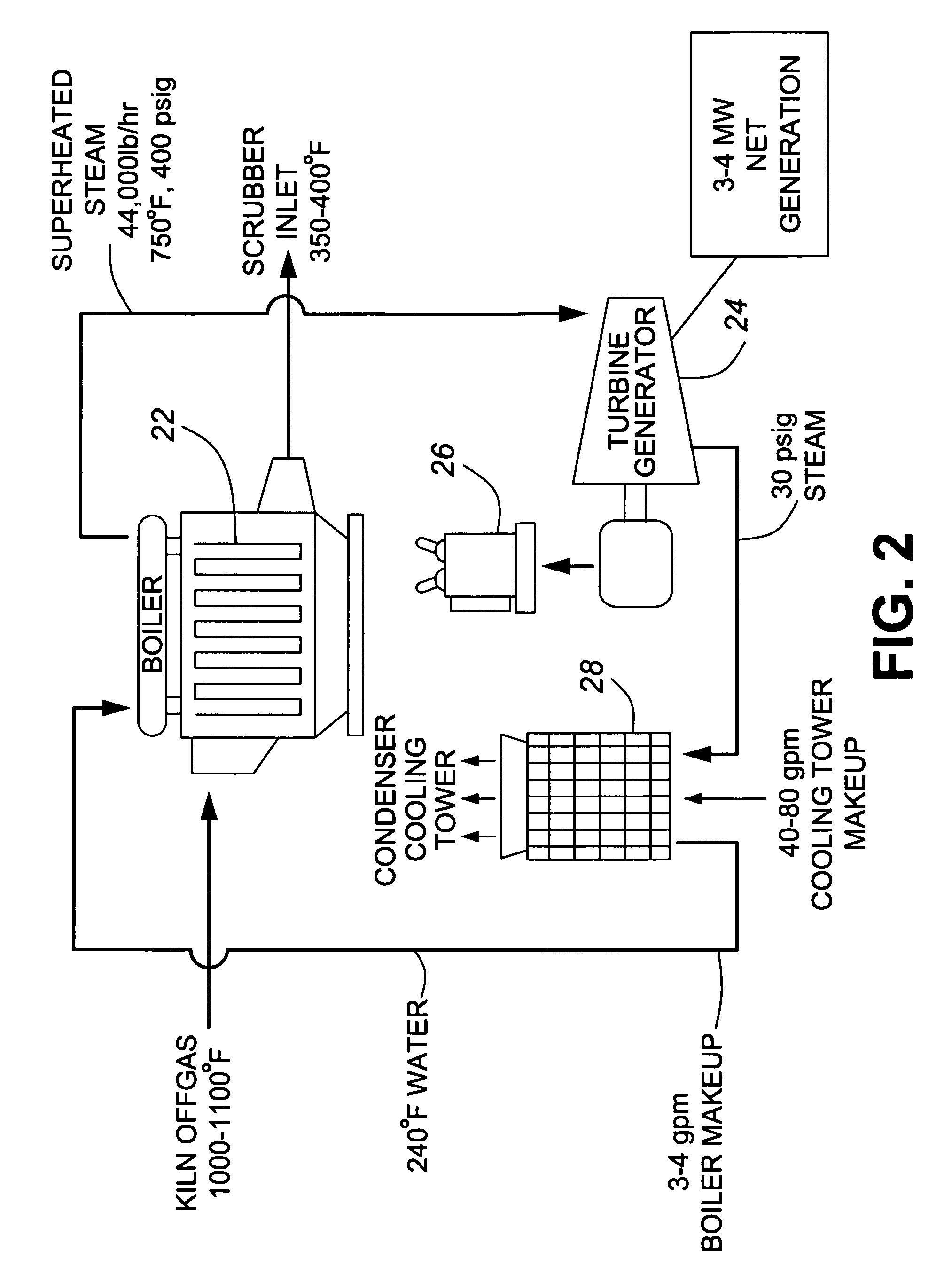
[0019]Referring now to the drawings and in particular FIG. 1 and FIG. 2, shown is an overall schematic illustration of the process according to one embodiment of the present invention. The process is globally referenced by numeral 10 and provides a straight kiln 12 of the rotary variety as is known in the art having an inlet 14 and outlet 16. The kiln is supported by supports 18 and these supports also function to permit rotation of the kiln. Specific details of this arrangement will not be discussed as any suitable kiln known for lime formulation can be selected and will be readily apparent to those skilled in the art.

[0020]The discharge or offgas exiting outlet 16 is transferred into a waste heat recovery power generation circuit, globally denoted by numeral 20. The circuit includes a boiler or reboiler 22, turbine generator 24 which turbine generator is in electrical communication with an electrical storage means 26. A condenser 28 is provided to condense any excess steam and rec...


PUM

PropertyMeasurementUnit
temperatureaaaaaaaaaa

Abstract

A process and system for recovering waste heat from a kiln used for lime or cement production. The system unifies the kiln, a waste heat recovery and power generation circuit and a dry scrubber for scrubbing the pollutants from the kiln offgas. Essentially, the system employs the boiler component of the waste heat recovery and power generation circuit as a heat exchanger to recover the waste heat from the kiln, which is used to drive the steam turbines. The heat absorption from the latter stage lowers the temperature of the kiln offgas sufficiently for optimum performance from the scrubber. The presence of lime particles in the offgas effectively protects the boiler tube surfaces from corrosion which would occur at optimum scrubber temperatures, and subsequently provides the lime required as a scrubbing medium for the dry scrubber. Further, the efficient scrubbing allows for the use of any fuel for firing the kiln inclusive of high sulphur content compounds. A process for effecting the technology is also provided.

Description

FIELD OF THE INVENTION[0001]The present invention relates to a process and system for recovering waste heat from a kiln used for lime or cement production fuel and more particularly, the present invention relates to the unification of known elements such as a kiln, a waste heat recovery and power generation circuit and a dry, semi-dry, or semi-wet scrubber (collectively “dry scrubber” herein) for scrubbing the pollutants from the kiln offgas, in a previously uncombined manner.BACKGROUND OF THE INVENTION[0002]It is well known that in North America, lime and cement is typically produced in rotary kilns. The primary energy consuming reaction in both processes is the conversion or calcination of limestone (CaCO3) to lime (CaO) also known as quicklime. The intense heat and energy needed to drive the reaction requires the use of fossil fuels. A byproduct of these processes is fine particulates trapped in air pollution control systems of rotary kilns commonly known as lime kiln dust (LKD) ...

Claims


Application Information

Patent Timeline
Patent Type & Authority Patents(United States)
IPC IPC(8): B01D53/50
CPCF27D17/008C04B2/10C04B7/4407F23J15/02F27B7/20F27D17/004F23J2217/101F23J2219/60Y02P40/40
Inventor SQUIRE, MERRILLCHARETTE, ALAIN
Owner GRAYMONT PA INC
Learn More