
Air powered vacuum apparatus

Active Publication Date: 2010-03-16
GUARDAIR CORP
View PDF19 Cites 15 Cited by
  • Summary
  • Abstract
  • Description
  • Claims
  • Application Information

AI Technical Summary

Benefits of technology

[0016]The invention has met the above needs. The invention provides an air powered vacuum apparatus having a spoil collecting container and an injector assembly in fluid communication with the container which creates a vacuum for drawing the spoil or material into the container. The injector assembly has a supersonic air nozzle associated with an injector that has a converging section, a straight section and a diverging section. The injector is in association with a tube which has a length that extends beyond an end of the diverging section of the injector assembly thereby creating a fluid flow under vacuum and reducing the sound level of the fluid being exhausted or ejected out of the diverging section of the injector assembly.
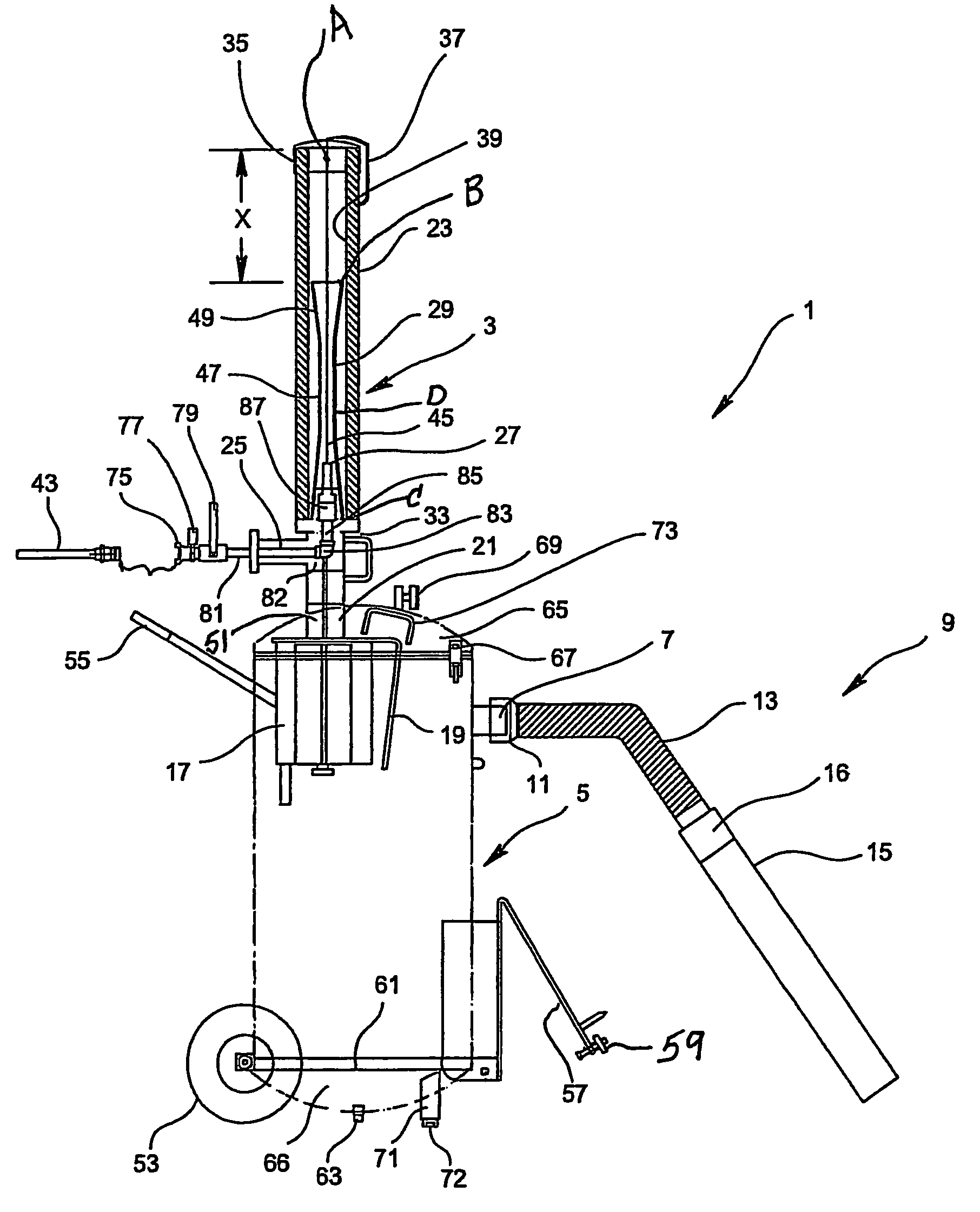
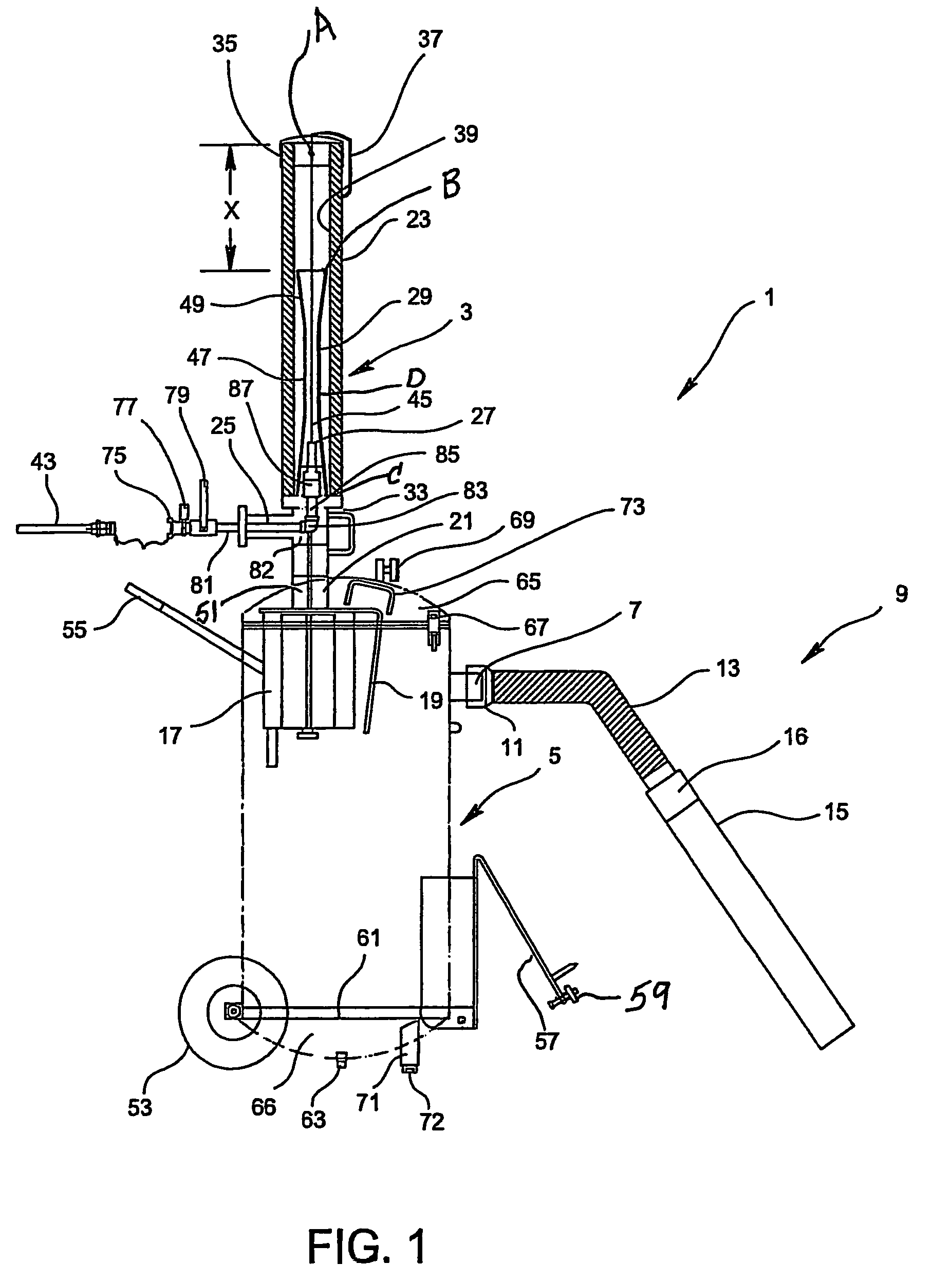
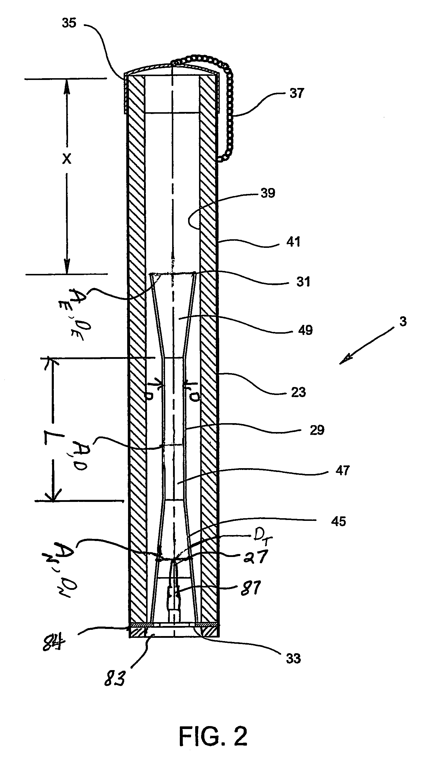
[0017]More specifically, the invention provides an air powered vacuum apparatus in an air vacuum excavation system comprising a container for drawing in and collecting spoil and an injector assembly connected to and in communication with the container and with a supply of compressed fluid and configured to convert the compressed fluid into supersonic fluid and then into subsonic fluid to create a vacuum for drawing the spoil into the container. The injector assembly comprises a conduit having a fluid inlet in communication with the container and adapted to be coupled to the compressed fluid supply a supersonic nozzle assembly connected to the compressed fluid supply for using the compressed fluid and ejecting supersonic fluid, an injector associated with the supersonic nozzle assembly and the conduit, comprising at least a converging section, a straight section, and a diverging section. The supersonic nozzle assembly is positioned inside the converging section of the injector. The straight section of the injector acts as a mixing chamber for mixing the supersonic fluid from the nozzle assembly with the fluid traveling from the container. The conduit includes a tee pipe and a tube and the tube has a straight length that extends beyond the diverging section of the injector for the reducing of the sound level of fluid being ejected from the diverging section of the injector of the injector assembly.
[0018]The present invention further provides an injector assembly for creating an air flow under vacuum and for reducing the sound level of the exhausting air comprising a conduit adapted to be coupled to a compressed air supply, a supersonic nozzle connected to the conduit for using the compressed air and converting it into supersonic air and for ejecting the supersonic air, an injector associated with an air source and being in fluid communication with the supersonic nozzle assembly, comprising a converging section, a straight section and a diverging section, and wherein the conduit includes a tube associated with the diverging section of the injector. The supersonic nozzle assembly is positioned inside the converging section of the injector assembly. The supersonic air ejected from the supersonic nozzle assembly travels into the straight section of the injector and mixes with the air from the air source. The tube has a length that extends beyond the diverging section of the injector for the reducing of the sound level of air traveling out of the diverging section of the injector of the injector assembly The supersonic air traveling through the injector creates the air flow under vacuum in the air source.
[0021]It is a further object of the invention to provide an improved air powered vacuum apparatus which can be efficiently and safely used in air vacuum excavation systems for excavating buried objects, such as pipes, cables, landmines, unexploded ordnance and tree roots. An advantage of this air vacuum excavation system is that it is also non-damaging to the buried objects.
[0022]A further object of the invention is to provide an improved air powered vacuum apparatus which provides a powerful vacuum for suctioning the spoil into the container and which reduces the sound level of the air being exhausted from the apparatus to acceptable levels.

Problems solved by technology

Commercial contractors, using conventional excavation equipment for locating buried utility equipment, such as wires, cables, etc., can have hundreds of accidents each year involving major property damage and loss of life.
Accidental severing of a transcontinental fiber optic line may cost the industry over $1.5 million per hour in lost revenue.
It has been demonstrated that the use of conventional excavation equipment may be too dangerous, resulting for example, in deterioration of buried drums or detonation of buried unexploded bombs and shells.
A 55 gallon drum full of soil can weigh over 700 pounds and can be very difficult to empty.
This system also employs a complicated arrangement with multiple jet pumps in parallel where compressed air passes through specially designed nozzles and venturi pipes at supersonic velocity.
Therefore, soils may not generally be free flowing materials that are easily removed or moved by conventional pneumatic transport.

Method used


Image

  • Air powered vacuum apparatus
  • Air powered vacuum apparatus
  • Air powered vacuum apparatus

Examples


Embodiment Construction

[0030]The air powered vacuum apparatus of the invention may be used in combination with a supersonic air digging tool for superior performance of the vacuum excavation system. This supersonic air digging tool may be similar to that disclosed in U.S. Pat. No. 5,782,414, U.S. Design No. D408,830, and U.S. Design No. D435,207, all of which are herein incorporated by reference in their entirety.

[0031]It is to be understood that the term “spoil” can be used interchangeably with the term “material” and as used herein encompasses any type of material that is excavated, which may include dirt, soil, debris, sand, gravel, rocks, water and contaminants.

[0032]FIG. 1 illustrates a first embodiment of the invention for the air powered vacuum apparatus 1 and includes an injector assembly 3 and container 5 (shown in phantom) for collecting and carrying excavated material or spoil. Container 5 may be a tank or drum and has a vacuum inlet 7 in fluid communication with container 5. A removable suctio...


PUM


Abstract

An air powered vacuum apparatus for use in an air vacuum excavation system creates a fluid flow under vacuum and reduces the sound level of the exhausting air. The apparatus comprises an injector assembly and a container for collecting spoil, i.e., dirt, sand, gravel, etc. drawn in from the excavation site. The vacuum is produced by an injector and a supersonic nozzle assembly in fluid communication with the container. The injector has converging, straight and diverging sections, and the supersonic nozzle assembly extends into the converging section. The supersonic air ejected from the nozzle assembly mixes with the air drawn up from the container, and the air mixture travels through the diverging section and out of the injector assembly and creates a vacuum in the container.

Description

CROSS REFERENCE TO RELATED APPLICATIONS[0001]This application is based on Provisional Patent Application No. 60 / 771,712 filed Feb. 9, 2006, on which priority of this patent application is based, and which is hereby incorporated by reference in its entirety.BACKGROUND OF THE INVENTION[0002]1. Field of the Invention[0003]The invention relates to a vacuum excavation system of the type which uses high velocity air to loosen the soil and a pneumatic vacuum to remove the loosened soil, and in particular, to an air vacuum excavation system having an improved air powered vacuum apparatus including an injector assembly for reducing the sound level of the supersonic air traveling through the air powered vacuum apparatus and creating a powerful vacuum in the spoil or material collection container for drawing the spoil or material into the container.[0004]2. Description of Related Art[0005]Vacuum excavation systems are well known. U.S. Pat. Nos. 4,776,781; 4,936,031; 5,140,759; 5,361,855; and 6...

Claims


Application Information

Patent Timeline
IPC IPC(8): E02F3/94
CPCE02F3/9206E02F5/003
Inventor NATHENSON, RICHARD D.NATHENSON, STEVEN J.
Owner GUARDAIR CORP
Learn More