Eureka AIR delivers breakthrough ideas for toughest innovation challenges, trusted by R&D personnel around the world.

Automatic gain control device having variable gain control interval and method thereof

a gain control and variable gain technology, applied in the direction of gain control, power management, wireless communication, etc., can solve the problems of deteriorating demodulation performance, difficult to use the above methods in a high-speed packet communication system, and inefficient operation of gain control operations of vga and lna that are usually used in commercial rf chips, etc., to achieve the effect of quick control of gain

Inactive Publication Date: 2010-03-09
ELECTRONICS & TELECOMM RES INST
View PDF4 Cites 11 Cited by
  • Summary
  • Abstract
  • Description
  • Claims
  • Application Information

AI Technical Summary

Benefits of technology

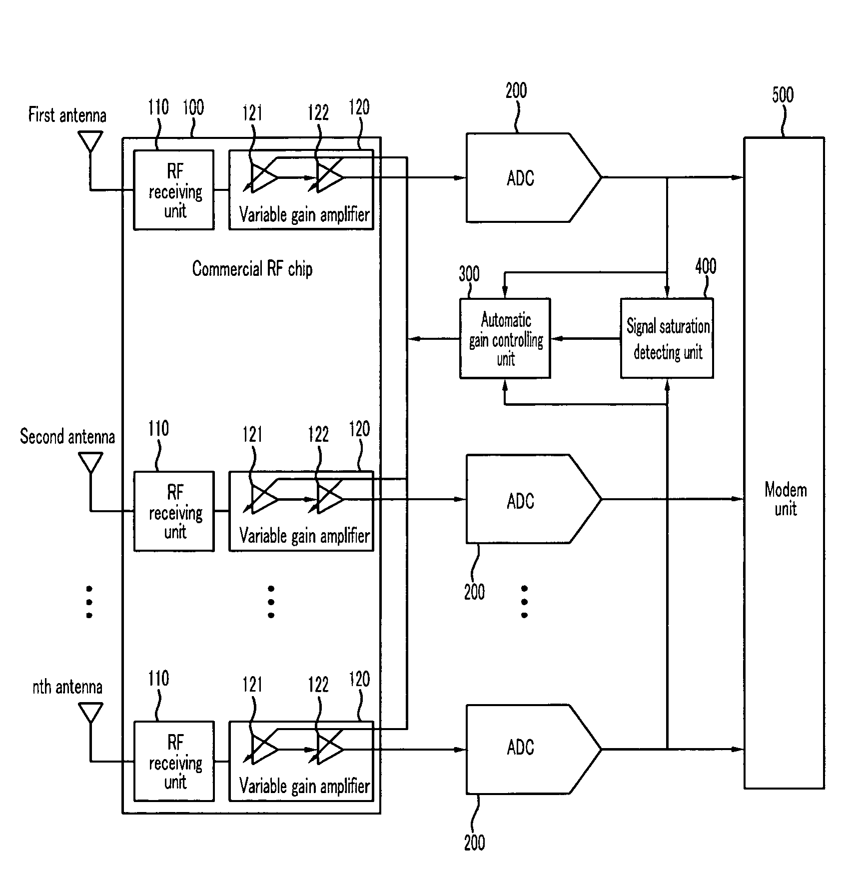
[0011]In addition, the present invention has been made in an effort to provide an automatic gain control device for establishing a gain control mode by a programmable register so that the automatic gain control device is used in a discrete RF module and a commercial RF chip, and for quickly controlling a gain by using an efficient gain control method and an LNA gain control state trace index when the commercial RF chip is used.

Problems solved by technology

In general, a signal is distorted in a digital realm when a gain of a received signal is out of a dynamic range of an analog to digital converter (A / D converter), and when the gain is set to be low, demodulation performance is deteriorated since a quantization noise is increased.
However, it is difficult to use the above methods in a high speed packet communication system since the initial convergent time thereof is long.
As described, in the prior art, gain controlling operations of the VGA and LNA that are usually used in the commercial RF chip may not be efficiently performed since a device for controlling an LNA gain state is not considered when a gain is controlled.
In addition, since complexity of the above methods is high, it is not efficient to use the methods in a multiple antenna system.

Method used


Image

  • Automatic gain control device having variable gain control interval and method thereof
  • Automatic gain control device having variable gain control interval and method thereof
  • Automatic gain control device having variable gain control interval and method thereof

Examples


Embodiment Construction

[0027]In the following detailed description, only certain exemplary embodiments of the present invention have been shown and described, simply by way of illustration. As those skilled in the art would realize, the described embodiments may be modified in various different ways, all without departing from the spirit or scope of the present invention. Accordingly, the drawings and description are to be regarded as illustrative in nature and not restrictive. Like reference numerals designate like elements throughout the specification.

[0028]Throughout this specification and the claims which follow, unless explicitly described to the contrary, the word “comprise”, and variations such as “comprises” or “comprising”, will be understood to imply the inclusion of stated elements but not the exclusion of any other elements.

[0029]In a single or multiplexing antenna wireless communication system, performance of a front end of a receiving terminal may greatly affect wireless communication system...


PUM


Abstract

An exemplary automatic gain control device includes: a radio frequency receiver for receiving a plurality of first signals through a plurality of antennas, respectively controlling gains of the plurality of first received signals, and outputting the plurality of the first signals having the controlled gain as a plurality of second signals; a signal saturation detecting unit for outputting a saturation index determination value when the number of plurality of second signals that are greater than a threshold value is greater than a predetermined number; and a gain controlling unit for comparing power values of the plurality of second signals to detect one power value, and outputting a gain value determined based on a detected power value and a saturation index determination value to the radio frequency receiver.

Description

CROSS-REFERENCE TO RELATED APPLICATION[0001]This application claims priority to and the benefit of Korean Patent Application No. 10-2005-0120851 filed on Dec. 9, 2005, and No. 10-2006-0049865 filed on Jun. 2, 2006, in the Korean Intellectual Property Office, the entire contents of which are incorporated herein by reference.BACKGROUND OF THE INVENTION[0002](a) Field of the Invention[0003]The present invention relates to an automatic gain control device having a variable gain control interval, and a method thereof. More specifically, the present invention relates to an automatic gain control device for a wireless local area network (WLAN) system having a multiplexing antenna and a single antenna, and a method thereof.[0004](b) Description of the Related Art[0005]In general, a signal is distorted in a digital realm when a gain of a received signal is out of a dynamic range of an analog to digital converter (A / D converter), and when the gain is set to be low, demodulation performance is...

Claims


Application Information

Patent Timeline
Patent Type & Authority Patents(United States)
IPC IPC(8): H04B1/06
CPCH04W52/52H03G3/3052
Inventor LEE, IL-GULEE, SOK-KYUYU, HEE-JUNGCHOI, EUN-YOUNGYOON, CHAN-HOSON, JUNG-BOLYU, DEUK-SUMIN, SEUNG-WOOKJEON, TAE-HYUNBANG, SEUNG-CHANHWANG, SEUNG-KU
Owner ELECTRONICS & TELECOMM RES INST
Why Eureka
Eureka Blog
Learn More