
Deep bitline implant to avoid program disturb

a bitline implant and program technology, applied in the field of deep bitline implants, can solve problems such as erroneous programming of the cell next to it, and achieve the effects of reducing program disturb, minimizing the detrimental impact of the device, and high energy

Active Publication Date: 2010-03-02
INFINEON TECH LLC
View PDF5 Cites 0 Cited by
  • Summary
  • Abstract
  • Description
  • Claims
  • Application Information

AI Technical Summary

Benefits of technology

The deep bitline implant process effectively minimizes short channel effects and prevents erroneous programming of adjacent memory cells, enabling higher packing density and improved performance in memory devices.

Problems solved by technology

A common known problem within the industry is that as one cell is programmed, the cell next to it is erroneously programmed as well, commonly referred to as “program disturb”.

Method used


Image

  • Deep bitline implant to avoid program disturb
  • Deep bitline implant to avoid program disturb
  • Deep bitline implant to avoid program disturb

Examples


Embodiment Construction

[0019]One or more aspects of the present invention are described with reference to the drawings, wherein like reference numerals are generally utilized to refer to like elements throughout, and wherein the various structures are not necessarily drawn to scale. In the following description, for purposes of explanation, numerous specific details are set forth in order to provide a thorough understanding of one or more aspects of the present invention. It may be evident, however, to one skilled in the art that one or more aspects of the present invention may be practiced with a lesser degree of these specific details. In other instances, well-known structures and devices are shown in block diagram or other form, in order to facilitate describing one or more aspects of the present invention.

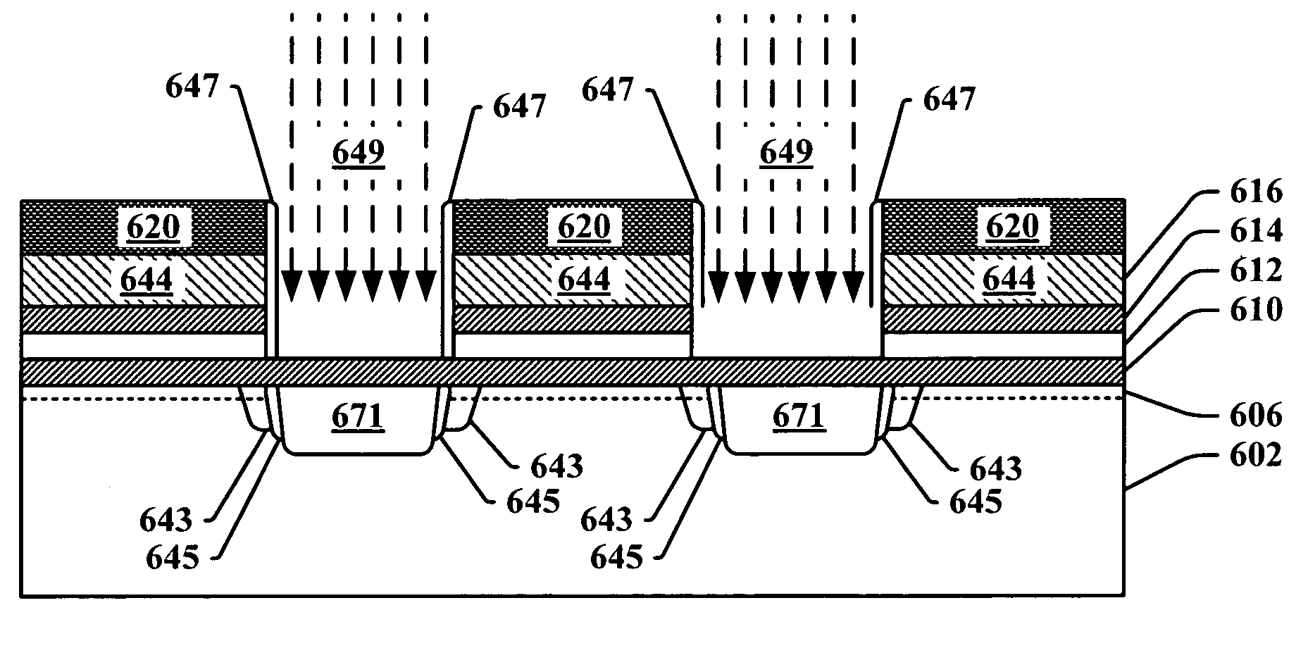
[0020]The present invention pertains to implementing a deep bit line implant process in forming a transistor based memory device in order to avoid program disturb. The process employs a deep bitline ...


PUM


Abstract

A method of forming at least a portion of a dual bit memory core array upon a semiconductor substrate, the method comprising performing front end processing, performing a first bitline implant, or pocket implants, or both into the first bitline spacings to establish buried first bitlines within the substrate, depositing a layer of the spacer material over the charge trapping dielectric and the polysilicon layer features, forming a sidewall spacer adjacent to the charge trapping dielectric and the polysilicon layer features to define second bitline spacings between adjacent memory cells, performing a deep arsenic implant into the second bitline spacings to establish a second bitline within the structure that is deeper than the first bit line, removing the sidewall spacers and performing back end processing.

Description

FIELD OF INVENTION[0001]The present invention relates generally to semiconductor processing and in particular to deep bitline implants in memory devices in order to avoid program disturb, for reducing voltage disturbances in non-selected memory cells while selected memory cells are being programmed.BACKGROUND OF THE INVENTION[0002]Several trends continue to be present in the semiconductor and electronics industry. Devices continue to be made smaller, faster and require less power while operating. One reason for this ongoing trend is that personal electronic devices are being fabricated that are designed to be smaller, and yet at the same time, packaged with greater memory capability. For example, cellular phones, personal computing devices, recorders, and personal sound systems are getting smaller while the memory capability, speed and computational power are expanding. In light of these trends, there is an ever increasing demand in the semi-conductor industry for smaller and faster...

Claims


Application Information

Patent Timeline
Patent Type & Authority Patents(United States)
IPC IPC(8): H01L27/112H01L21/336
CPCG11C5/02G11C5/06H01L27/115H01L27/11568H10B69/00H10B43/30
Inventor THURGATE, TIMOTHYHE, YIKWAN, MING-SANGLIU, ZHIZHENGWANG, XUGUANG
Owner INFINEON TECH LLC
Learn More