
Flame-resistant closure

a technology of flame-resistant closures and closures, applied in the field of flame-resistant closures, can solve the problems of high implementation costs, insufficient measures to meet the more stringent flame-protection guidelines, and the use of carbon fiber materials, which has, however, proved very costly, and achieves low flammability. , the effect of economic production

Active Publication Date: 2010-03-02
GOTTLIEB BINDER
View PDF15 Cites 4 Cited by
  • Summary
  • Abstract
  • Description
  • Claims
  • Application Information

AI Technical Summary

Benefits of technology

[0007]An object of the present invention is to provide an improved flame-retardant closure which meets increased requirements for low flammability and which can be economically produced.
[0009]In one especially preferred embodiment of the flame-retardant closure according to the present invention, the substrate layer is connected to the backing fabric by an adhesive layer. Preferably, the backing fabric has a finish ensuring fixing of the backing fabric with the individual threads. To provide good further processing capacity of the closure, in one preferred embodiment the substrate layer on its side facing away from the backing fabric has a connecting part. This connecting part can be made as a woven or non-woven material, and allows a good connection of the closure to outside parts such as cushion covering materials or cushion foam parts.

Problems solved by technology

Although the known closure on its top can be completely surrounded by the flame-retardant medium, or at least is formed partially of the flame-retardant medium itself, these measures are not currently adequate to meet the more stringent flame protection guidelines.
This solution forms a flame-retardant closure with very good action, but can be expensive in implementation, especially with respect to placing the U-shaped fastening elements in the substrate layer.
Although in the known solution both the loop part and also the hook part have a textile character so that they can be processed like conventional textile hook and loop closures, in particular sewn on, their flame resistance far exceeds that of textile hook and loop closures of the conventional type, specifically 1,000° C. The use of carbon fiber materials has, however, proven very costly, since carbon material is only available to a limited degree, at least for the present.

Method used


Image

  • Flame-resistant closure
  • Flame-resistant closure

Examples


Embodiment Construction

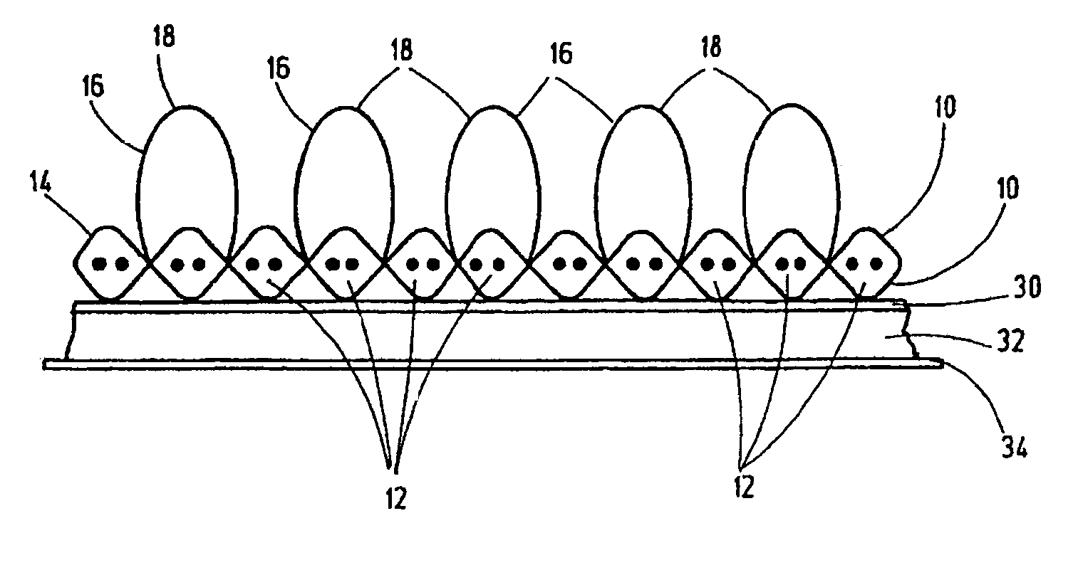
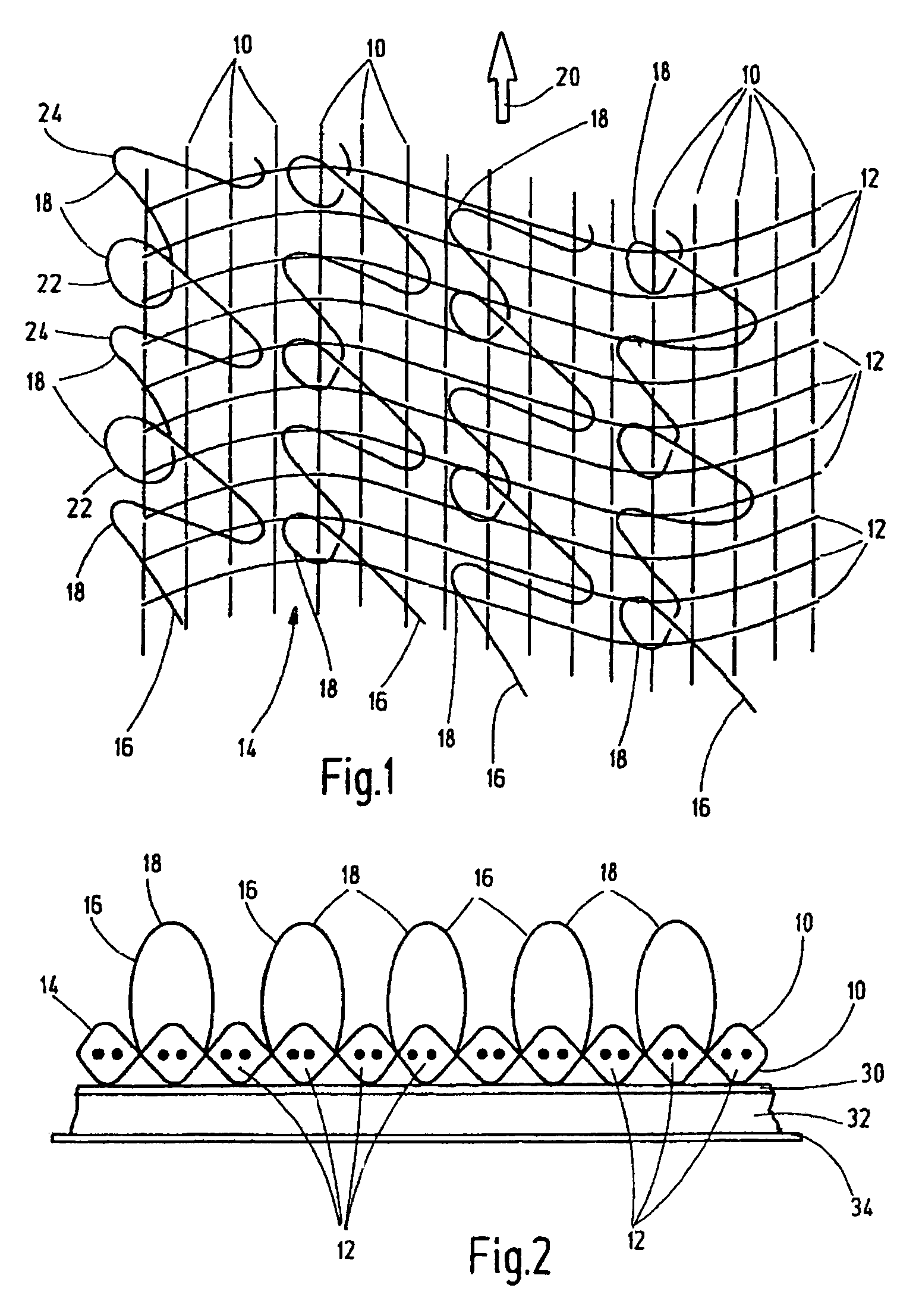
[0015]FIG. 1 shows by an extract a top view of a two-dimensional hook and loop closure part which can be optionally lengthened within the plane of the figure in both directions or either direction of the figure. The geometrical dimensions of the sheet article are dependent on the specifications of the weaving means on which the hook and loop closure part is made. Especially for later use, these closure parts are manufactured as hook and loop closure strips wound into rolls (not shown). The closure part includes warp threads 10 and weft threads 12 woven in a transverse arrangement to one another to form the backing fabric 14 for the hook and loop closure part. The backing fabric 14 is provided with functional threads 16 in the manner of pile threads to form a further part of the backing fabric. The functional threads 16 form the individual closure elements 18 for the two-dimensional hook and loop closure part.

[0016]Viewed in the direction of FIG. 1, on its top the production directio...


PUM

PropertyMeasurementUnit
Electrical resistanceaaaaaaaaaa
Heataaaaaaaaaa
Flammabilityaaaaaaaaaa

Abstract

A flame-resistant closure includes at least one closing part having at least one two-dimensional backing fabric (14) of warp threads (10) and weft threads (12) and having functional threads (16) on the right side of the backing fabric (14). The functional threads at least partially extend through the backing fabric (14), and form the closing elements (18). The backing fabric (14) is of the non-flame-resistant type. At least some sections of the backing fabric reverse side include a substrate layer (32) with a substantially inflammable medium and / or with an active extinguishing medium. This closure meets even high demands on inflammability.

Description

FIELD OF THE INVENTION[0001]The present invention relates to a flame-resistant closure in the manner of a fastening system comprising a two-dimensional hook and loop closure part. The closure elements corresponding to one another can be caused to detachably engage. Fastening systems such as these have also become known under the trademark name Velcro or Velcro hook and loop closures.BACKGROUND OF THE INVENTION[0002]Woven hook and loop closure parts, whose warp, weft, and functional threads may be formed of textile fibers. Plastic or metal fibers are also readily available on the market in a host of embodiments. The functional threads in the backing fabric of warp and weft threads form loop-shaped interlocking elements, provided they are formed from multifilament threads. If the functional threads are formed from monofilament fibers, these closed loops are cut apart or thermally separated from one another to form closure hooks which can be caused to engage the correspondingly made fl...

Claims


Application Information

Patent Timeline
IPC IPC(8): B32B3/06D03D27/00
CPCA44B18/0023A44B18/0073A44B18/0092Y10T428/24017Y10T428/24008Y10T442/3976
Inventor POULAKIS, KONSTANTINOS
Owner GOTTLIEB BINDER
Learn More