De-pressurization scheme for chromatography columns

a separation column and depressurization scheme technology, applied in the direction of fluid pressure control, separation process, instruments, etc., can solve the problems of high waste solvent production, premature breakage, slow effective process time of samples, etc., to reduce the outlet pressure of the column, and reduce the negative effect of rapid pressure loss

Active Publication Date: 2010-03-02
THAR INSTR
View PDF26 Cites 4 Cited by
  • Summary
  • Abstract
  • Description
  • Claims
  • Application Information

AI Technical Summary

Benefits of technology

[0009]The preferred and alternative embodiments overcome the problems described above of potential damage to separation columns, such as a packed chromatography column, caused by rapid or severe pressure loss. The preferred embodiment is a process for de-pressurization of the column after such a pressure loss has occurred and the system has stopped pumping mobile phase into the column. Once flow from the pump has ceased, the flowstream in the column is in a static condition from the lack of pressure forces and flow from the pump. The remaining pressure causing flow out of the column is due to expansion of the mobile phase caused by the decrease in pressure, not because of pressure applied by pumps. The outlet pressure of the column is adjusted so that the expansion of the flowstream that occurs at pressure loss can be controlled to flow out of the column. The de-pressurization scheme decreases column outlet pressure in steps that each maintain outlet pressure for time period before decreasing the pressure to the next pressure setpoint. This process allows the inlet pressure of the column to decrease at a controlled rate of decrease of the outlet pressure. The decrease in pressure with setpoints reduces the negative effects of rapid pressure loss on the column and thereby reduces potential failure and damage to the column.
[0010]The effect of the controlled de-pressurization is to avoid any rapid expansion of the mobile phase in the column. It also avoids freezing the packed media, frit, fittings, and then subjecting them to a high pressure force caused by uncontrolled expansion of the gas in the mobile phase exposed to lower pressures.

Problems solved by technology

While process and collection speeds are faster than LC, drawbacks to HPLC include high waste solvent production and slow effective process time for samples due to removal of solvent and water from collected sample fractions.
In the prior art, columns are often machine tooled at the ends, which causes stresses and weakening at the ends that can cause premature breakage.
Problems occur with chromatography columns that are caused by rapid and / or uncontrolled pressure loss occurring downstream of the outlet side of the column in a process system.
Since frits are commonly metal that are fitted into a column with a plastic ring, the freezing of the metal and the freezing of the plastic ring will cause differential swelling between the frit and its fittings.
Further, if pressure is instantly relieved in a column of packed media bed containing a flowstream of carbon dioxide, dry ice will form in the media bed itself and disturb the packing consistency of the bed.
The combination of differential shrinking of the frit and fittings and disturbance in the bed caused by expanding mobile phase under pressure force towards the column outlet could cause loss of packed media past the frit.
The instant release of pressure from an expanding mobile phase in a column can also damage the frit itself.
A frit that is instantly frozen by dry ice becomes brittle, and its channels normally used for distributing fluid flowstreams become clogged up with dry ice, which blocks all flow out of the column.
With a clogged outlet to the column and the column media still under rising high pressure, the failure of the frit along with damage to column media can occur.
In larger columns, the larger diameter frit is even more susceptible structural to deflection caused by clogging and pressure from the packed media.
If the frit freezes and becomes brittle, it can crack or break upon deflection from the upstream pressure forces attempting to escape the column.
Further, the pressure differential between the ends of the column can cause an impulse force directly onto the frit whether or not the channels in the frit freeze, causing potential failure of the frit and its fittings.

Method used


Image

  • De-pressurization scheme for chromatography columns
  • De-pressurization scheme for chromatography columns
  • De-pressurization scheme for chromatography columns

Examples


Embodiment Construction

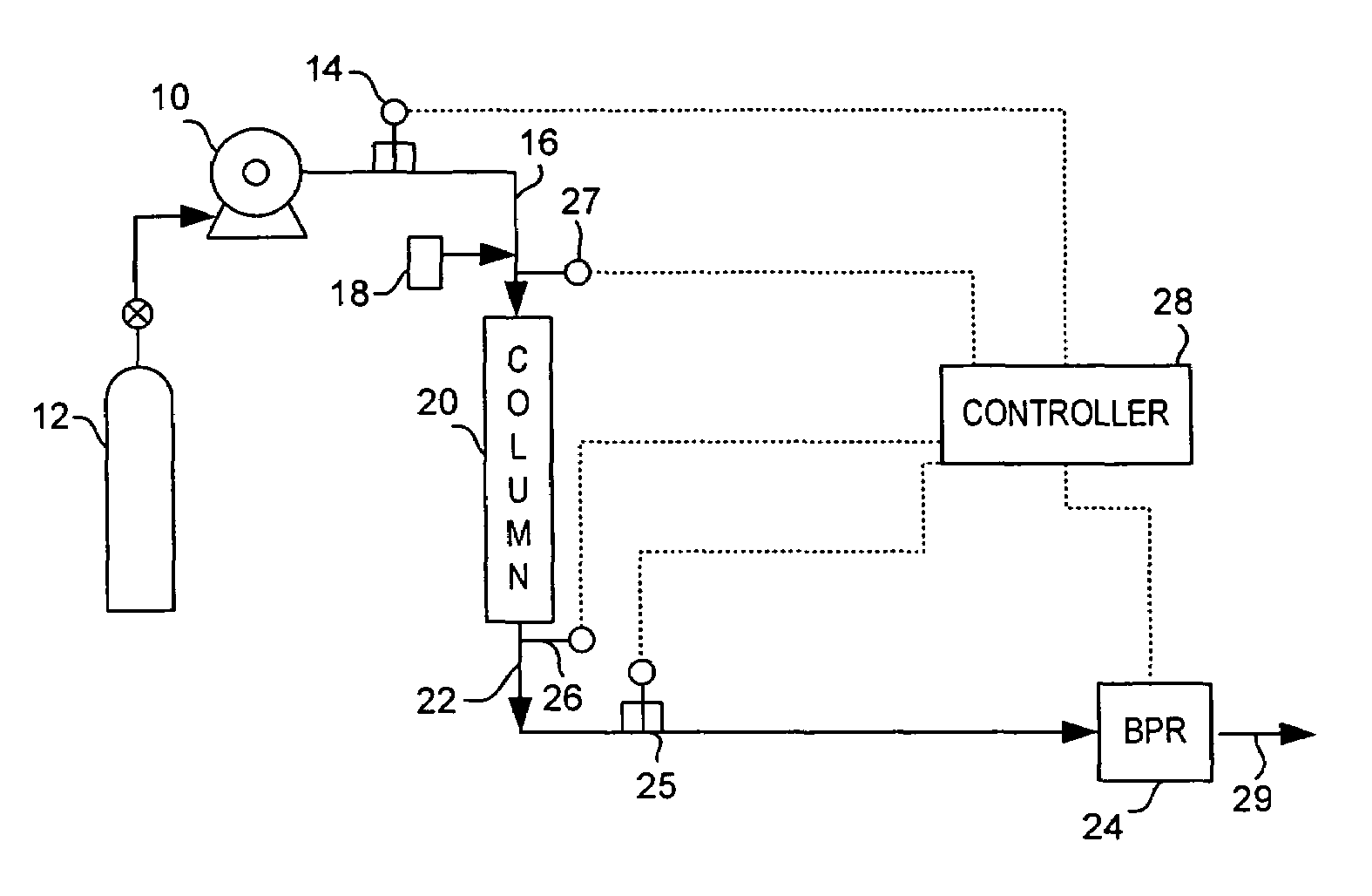
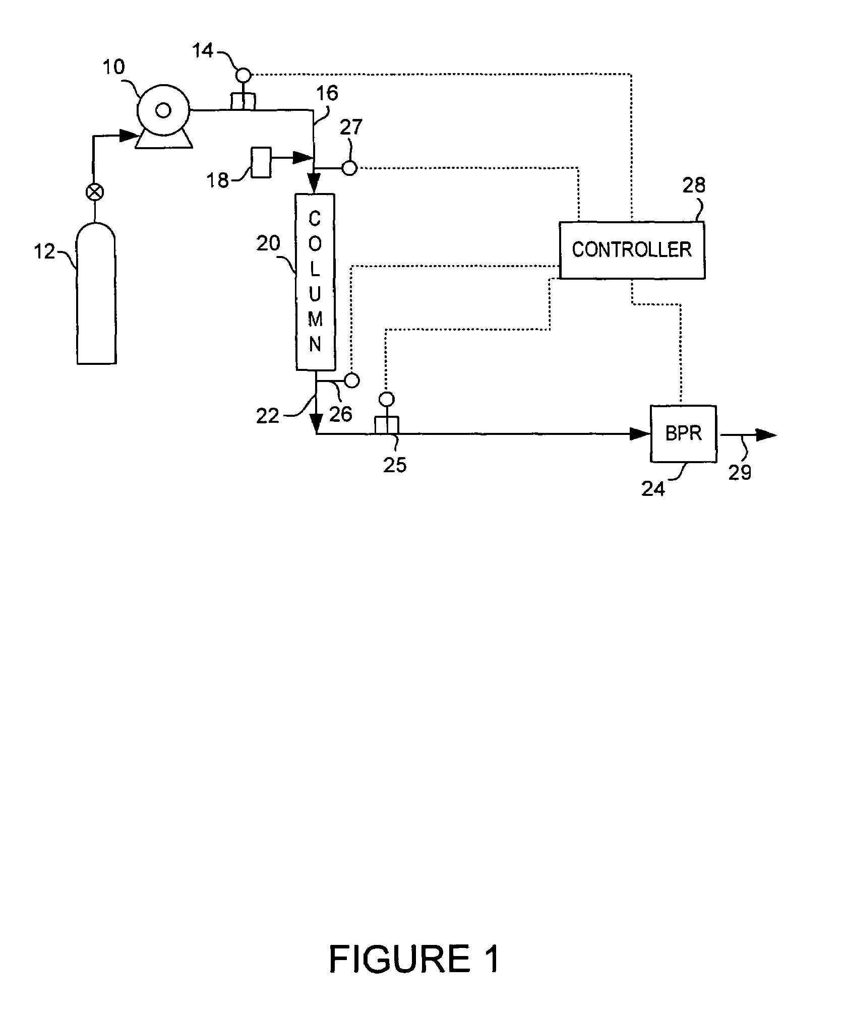
[0017]FIG. 1 illustrates a preferred chromatography system implementing the de-pressurization process of the preferred embodiment. The figure shows a chromatography system, such as a liquid chromatography (LC), gas chromatography, high performance liquid chromatography (HPLC), or supercritical fluid chromatography system. However, it is understood that any system utilizing a device handling a mobile phase flowstream under pressure with a potential for damage to the device if pressure is lost could benefit from the present invention.

[0018]The system includes at least one pump 10 to draw liquid or gaseous mobile phase from one or more tanks 12. Pump 10 may include multiple pumps drawing from different tanks of modifier liquid and gas for mixing as a mobile phase fluid at high or supercritical pressure conditions. Depending up on the type of chromatography system, mobile phase can be pure or modified fluids including binary and tertiary fluids containing additives. As examples, pure fl...


PUM

PropertyMeasurementUnit
diameteraaaaaaaaaa
diameteraaaaaaaaaa
pressureaaaaaaaaaa

Abstract

A depressurization process for a packed separation column is provided where the column system experiences a rapid and / or severe drop in pressure that could potentially damage column components. The process provides a safe de-pressurization of the column on the outlet side by decreasing the outlet pressure in controlled steps while allowing the inlet pressure of the column time to lower after each decreased step.

Description

FIELD OF THE INVENTION[0001]The present invention relates to a process for controlled de-pressurization of a separation column in a chromatography system.BACKGROUND OF THE INVENTION[0002]In the technology of chromatography, the separation and collection of fractions of chemical compounds vary in process, instruments, and production capability. However, each type of system uses at least a fluid, called a mobile phase, that is pumped into the head of a separation column. A sample containing one or more chemical compounds is carried by the mobile phase flowstream through the column. The media in a column delays certain compounds from exiting the outlet of the column according to different retention times. These separated compounds can be detected and graphed as a “peak” of the injected sample. If the same temperature, pressure, flowrate, and injection composition is maintained in the chromatography system, then repeated injections into the column of the same mixture can produce repeate...

Claims


Application Information

Patent Timeline
Patent Type & Authority Patents(United States)
IPC IPC(8): B01D15/08
CPCB01D15/163G01N30/32G05D16/202Y10T137/0396Y10T137/2278
Inventor WIKFORS, EDWIN E.FOGELMAN, KIMBER D.
Owner THAR INSTR
Why Eureka
Try Eureka