
Auto creeper tread

a technology of creeper tread and auto, which is applied in the direction of roads, vehicle components, construction, etc., can solve the problems of automobiles usually getting stuck or trapped, automobiles usually skid or sinking into the ground, and drivers are susceptible to intolerable distress, so as to reduce the weight of the skid-proof device, increase the friction, and reduce the weight of the skid-proof pad

Inactive Publication Date: 2010-03-02
SHENZHEN CESS TECH
View PDF10 Cites 2 Cited by
  • Summary
  • Abstract
  • Description
  • Claims
  • Application Information

AI Technical Summary

Benefits of technology

"The present invention provides an auto creeper tread that can help automobiles get out of dangerous roads without needing to seek traction force from a third party. The tread includes a skid-proof pad and a bar-shaped track designed for the width of an automobile wheel. The skid-proof pad has three or four rows of circular holes that increase friction with the ground and the tires, and also reduce the weight of the pad. Reinforcing grooves are also included to prevent the pad from being bent or deformed. The track is a high-strength fabric strap that is fastened to the skid-proof pad and the tire lock. The tire lock is engaged with the track and a tire lock can be used to get the automobile out of a pit. The skid-proof pad can also serve as a resting pad for drivers and passengers, or a temporary pad for repairing an automobile."

Problems solved by technology

At present, automobiles usually get stuck or trapped in the following terrains: deserts, swamps, muddy roads and snow.
Automobiles usually skid or sink into the ground when they get stuck.
In situations when automobiles get stuck into the ground and cannot make an escape, drivers could only seek help from other automobiles to give it a tow.
Sometimes, if the incident occurs in a remote area far away from people or towns, drivers would be susceptible to intolerable distress, delay in schedule and disturbance in work.
It is deficient in that it is useless if the automobile sinks into a deeper pit or if any of the tires loses contact with the ground.
Its disadvantage is that it must have an anchor point.
However, it requires much effort and is easily susceptible to failure due to the soft soil texture at the position of the anchor point.
Moreover, a large number of accessories such as tree strap, pulley assembly, U-shaped hook and leather gloves are required when using a winch.
An electric winch can only continuously operate for several minutes.
Therefore, it is necessary to reduce as much as possible the rotating time of a winch, or the generator would be damaged due to overheating or the accumulator cell would be subjected to over discharge.
Another disadvantage is that a sufficient safe space in front of or behind the automobile to be rescued is required for placing an anchor point.
However, there is no guarantee to have such a large empty area at places where automobiles easily get stuck.
Differential lock is deficient in that it can only be used on wet and slippery roads.
When the automobile gets on dry and firm roads, it is necessary to disengage the differential lock immediately, or the gears would be damaged.
Moreover, when the tires of the automobile lose contact with the ground and the chassis of the automobile is lifted, a differential lock could not help much with the rescue.
Currently, the majority of automobiles are not designed for the installation of differential locks.
Therefore, differential locks are not common rescuing tools.
Its disadvantage is that it becomes useless when the automobile sinks deep into the ground, especially when the chassis of the automobile is being lifted and thereby causing the tires to lose contact with the ground.
However, when an automobile sinks deeper into the ground, especially when the chassis of the automobile is being lifted and thereby causing the tires to lose contact with the ground, the friction generated between the antiskid plate and the tires is far from being able to overcome the resistance generated by the adhesion of the automobile towards the slough, snow and sand.
The automobile was unable to be retrieved despite that the casing and the chassis thereof are substantially detached from each other.
It is even impossible for relevant anti-sink devices derived from antiskid plate to generate sufficient traction to get the automobile out of the area where it gets stuck.

Method used


Image

  • Auto creeper tread
  • Auto creeper tread

Examples


Embodiment Construction

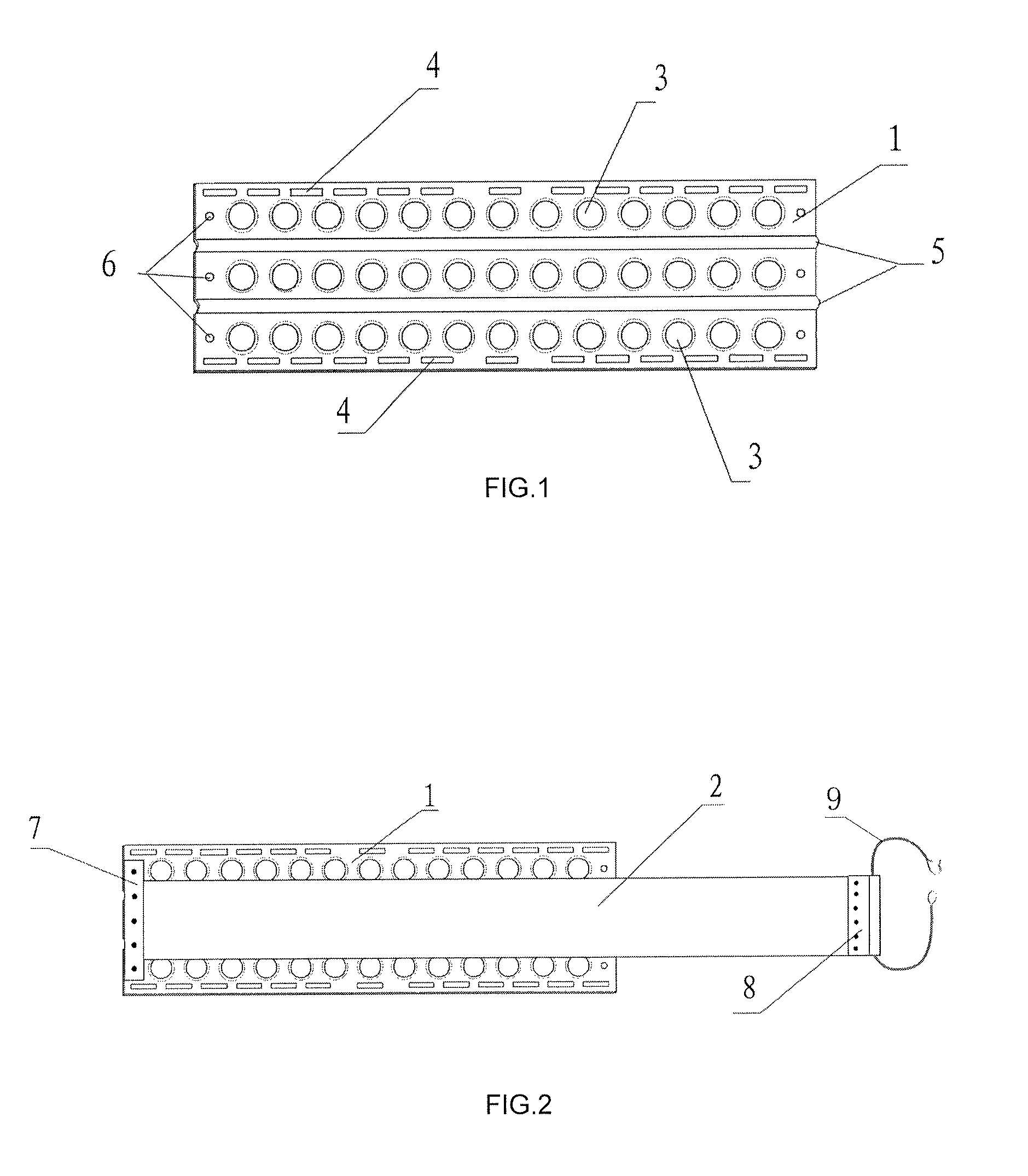
[0017]As illustrated in the accompanying drawings, the present invention is an auto creeper tread which comprises a rectangular skid-proof pad 1 and a bar-shaped track 2 designed according to the width of an automobile wheel. Three or four rows of circular holes 3 are disposed in an orderly manner on the skid-proof pad 1. The edge of each of the circular holes 3 protrudes outwards. Two rows of rectangular holes 4 are disposed on two sides of the skid-proof pad 1. Two protruding reinforcing grooves 5 are disposed in the middle of the skid-proof pad 1. A row of small circular holes 6 are disposed on each of the two ends of the skid-proof pad 1. The track 2 is a Tetoron fabric strap of high strength and wear resistance. The track 2 is engaged with the skid-proof pad 1 by placing an end of the track 2 on top of the small circular holes 6 of the skid-proof pad 1, fastening with a press plate 7 and fixed by means of rivets. The other end of the track 2 is disposed with a clamping plate 8 ...


PUM


Abstract

An auto creeper tread has the following features: three or four rows of circular holes disposed in an orderly manner on a skid-proof pad, wherein, the edge of each of the circular holes protrudes outwards; two rows of rectangular holes disposed on two sides of the skid-proof pad; two protruding reinforcing grooves disposed in the middle of the skid-proof pad; a row of small circular holes disposed on each of the two ends of the skid-proof pad; a track connected to the skid-proof pad by rivets; and a tire lock connected to one end of the track with a clamping plate. The auto creeper tread is designed to provide anti-sink and anti-skid solutions for automobiles.

Description

BACKGROUND OF THE INVENTION[0001]The present invention relates to a self-rescue apparatus for automobiles and more particularly pertains to an auto creeper tread used for automobile self-rescue.[0002]At present, automobiles usually get stuck or trapped in the following terrains: deserts, swamps, muddy roads and snow. Automobiles usually skid or sink into the ground when they get stuck. In situations when automobiles get stuck into the ground and cannot make an escape, drivers could only seek help from other automobiles to give it a tow. Sometimes, if the incident occurs in a remote area far away from people or towns, drivers would be susceptible to intolerable distress, delay in schedule and disturbance in work. It is most common to make an escape by means of tow truck. Towing is advantageous in that it is simple and easy to perform as it only requires one other automobile and a trailer rope. To prevent an automobile from getting stuck, a metal chain in the form of continuous enclos...

Claims


Application Information

Patent Timeline
Patent Type & Authority Patents(United States)
IPC IPC(8): E01B23/00
CPCB60C27/00
Inventor CEN, SHIWEI
Owner SHENZHEN CESS TECH
Learn More