
Multilayer capacitor and electronic device

a multi-layer capacitor and electronic device technology, applied in the direction of fixed capacitors, fixed capacitor details, capacitors, etc., can solve the problems of difficult to achieve a desired resonance frequency and impedance, and difficult to realize a low impedance characteristic across a wide band, so as to increase the number of resonance frequencies of multi-layer capacitors, low impedance, and wide band

Active Publication Date: 2010-02-23
TDK CORPARATION
View PDF20 Cites 18 Cited by
  • Summary
  • Abstract
  • Description
  • Claims
  • Application Information

AI Technical Summary

Benefits of technology

The present invention provides a multilayer capacitor and electronic device that can achieve low impedance across a wide band. This is achieved by integrating a plurality of capacitors with different capacitances, which allows for a plurality of resonance frequencies. The distance between the first lead portions of the internal electrodes and the second terminal electrodes is different for each type of internal electrode, resulting in different equivalent series inductance and capacitance for each port. By adjusting these factors, the resonance frequencies of the capacitor portions can be controlled minutely, allowing for a wider band of low impedance. The plural types of internal electrodes can be divided into sub-portions to increase the number of resonance frequencies and achieve low impedance across a wider band. The invention also provides a method for easily adjusting the resonance frequencies of the capacitor portions.

Problems solved by technology

It is, however, not easy to achieve a desired resonance frequency and impedance, by integrally arranging a plurality of capacitors with different capacitances as in the above-described conventional technology.
Therefore, it is difficult to realize a low impedance characteristic across a wide band.

Method used


Image

  • Multilayer capacitor and electronic device
  • Multilayer capacitor and electronic device
  • Multilayer capacitor and electronic device

Examples


first embodiment

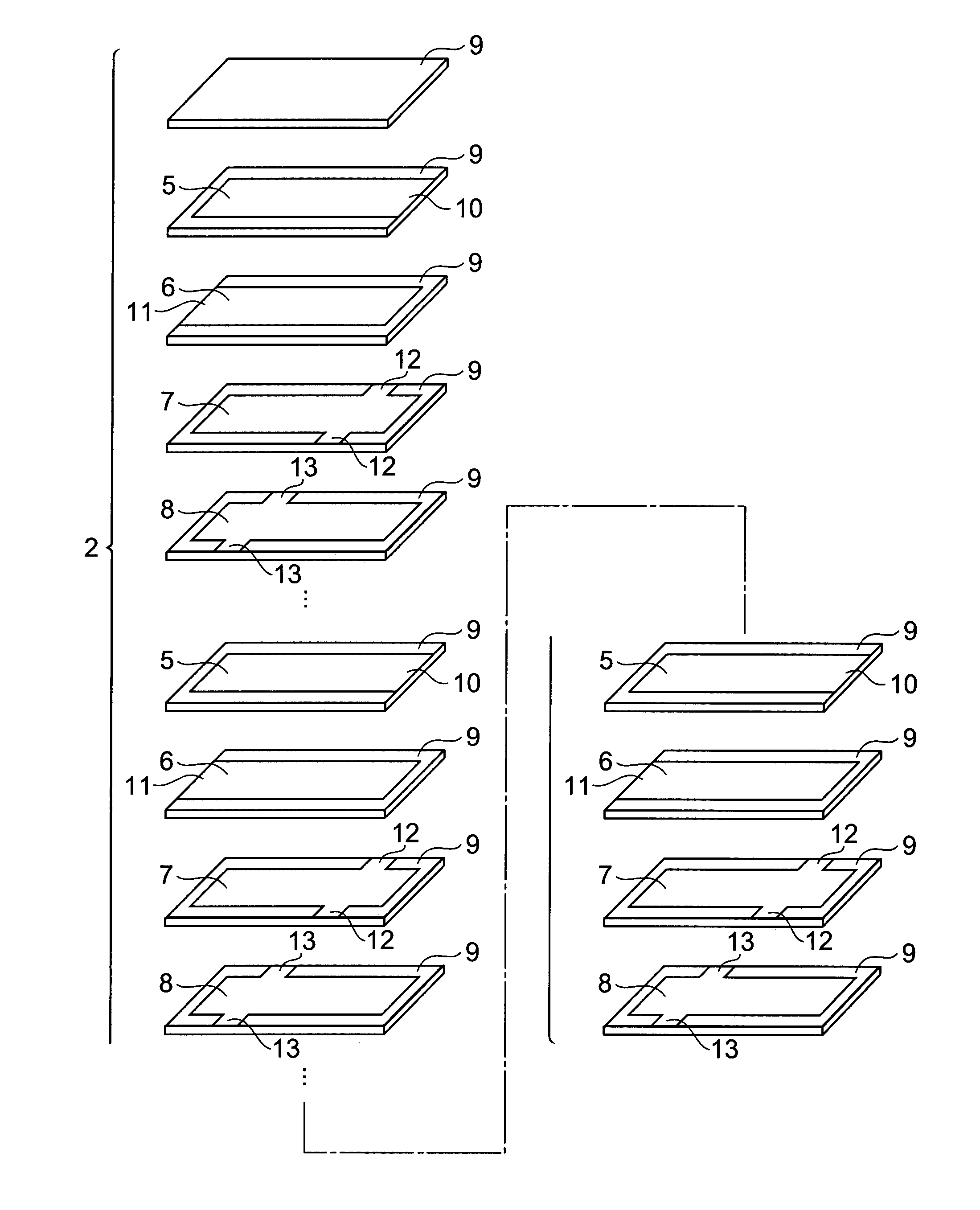
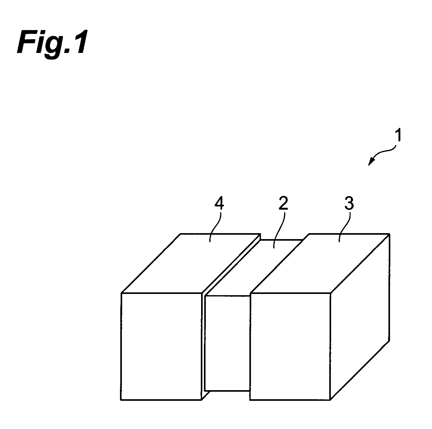
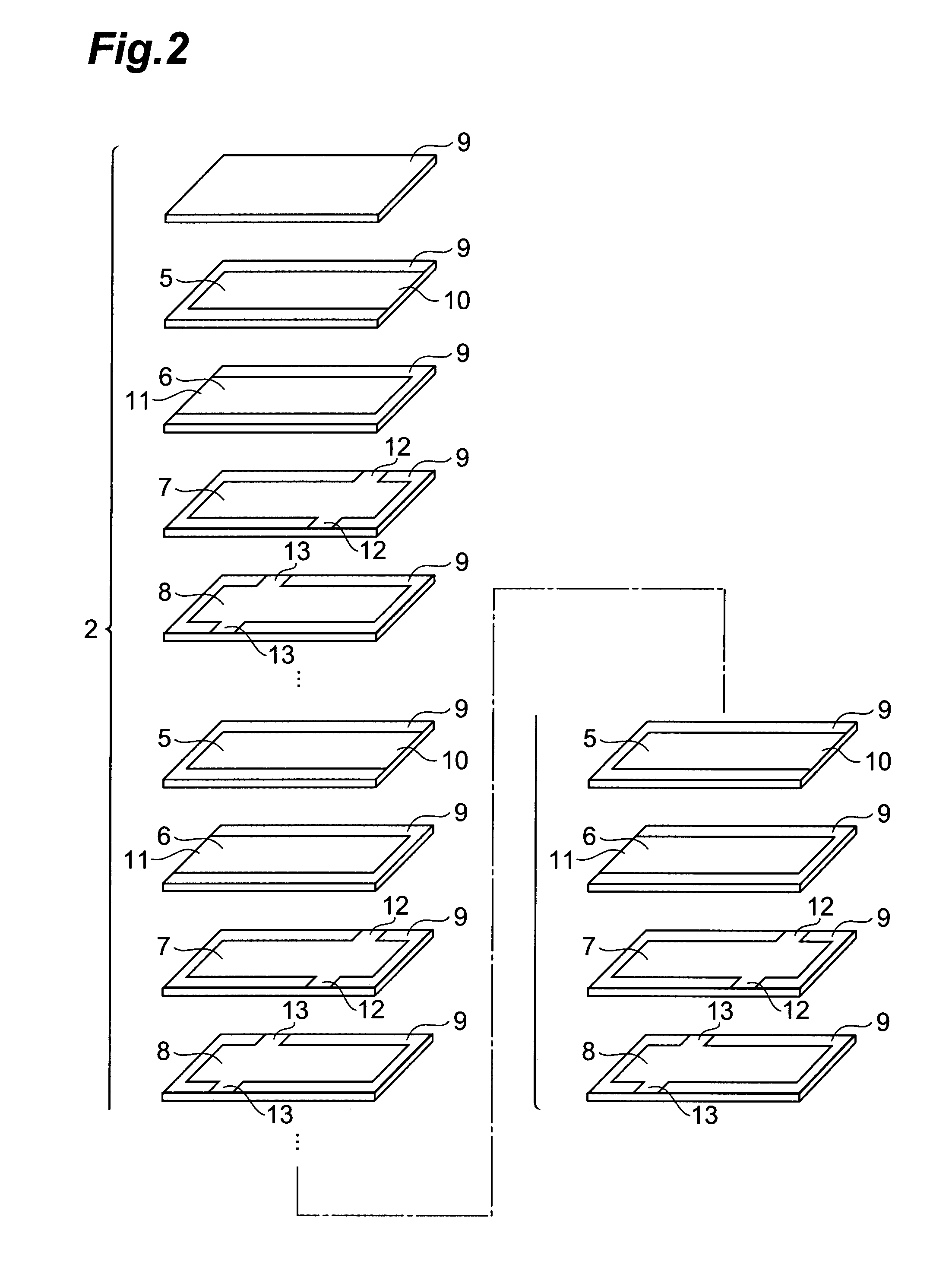
[0032]FIG. 1 is a perspective view showing the multilayer capacitor according to the In the same drawing, the multilayer capacitor 1 of the present embodiment has a laminate body 2 of a rectangular parallelepiped shape (which encompasses a nearly rectangular parallelepiped shape as well as a perfect rectangular parallelepiped shape), a terminal electrode 3 disposed on one longitudinal end side of this laminate body 2, and a terminal electrode 4 disposed on the other longitudinal end side of the laminate body 2.

[0033]The terminal electrode 3 is provided so as to cover one end face of the laminate body 2 and one-end-face-side portions in the four side faces of the laminate body 2, and the terminal electrode 4 is provided so as to cover the other end face of the laminate body 2 and other-end-face-side portions in the four side faces of the laminate body 2. The terminal electrodes 3, 4 are made, for example, by forming a Ni-plated layer and a Sn-plated layer in order on a baked electro...

third embodiment

[0069]Namely, the multilayer capacitor has the four resonance frequencies fr1-fr4, as in the third embodiment, and thus can achieve the low impedance across a sufficiently wide frequency band.

[0070]The above-described embodiment used the four types of internal electrodes connected to the terminal electrode 4, but the types of internal electrodes connected to the terminal electrode 4 may be three types, or five or more types, of course.

[0071]FIG. 10 is a sectional view showing the internal electrode layers in the multilayer capacitor according to the fifth embodiment. In the drawing, identical or equivalent elements to those in the first embodiment will be denoted by the same reference symbols, without redundant description.

[0072]In the same drawing, the laminate body 2 of the multilayer capacitor of the present embodiment has a structure in which internal electrode layers 51-53 are alternately laminated from the bottom in each of plural groups with a dielectric layer 9 in between.

[0...

fourth embodiment

[0083]An internal electrode layer 61 is composed of an internal electrode 48 similar to that in the An internal electrode layer 62 is composed of internal electrodes 63, 64 formed alongside in the longitudinal direction of the laminate body 2. The internal electrode 63 has a pair of lead portions 65 led to the side faces 2c, 2d of the laminate body 2 and connected to the terminal electrode 4. The internal electrode 64 has a lead portion 66 led to the side faces 2c, 2d of the laminate body 2 and connected to the terminal electrode 4. The internal electrode 63 has an area larger than the internal electrode 64.

[0084]In the multilayer capacitor of this configuration, there are capacitor C1 and capacitor C2 formed. The capacitor C1 is composed of the internal electrodes 48, 63 of the mutually opposite polarities, and the dielectric layer 9 present between them. The capacitor C2 is composed of the internal electrodes 48, 64 of the mutually opposite polarities, and the dielectric layer 9 ...


PUM


Abstract

A multilayer capacitor has a laminate body in which a first internal electrode and a second internal electrode are alternately laminated with a dielectric layer in between, a first terminal electrode provided on one end side of the laminate body, and a second terminal electrode provided on the other end side of the laminate body. The first internal electrode has a first lead portion connected to the first terminal electrode. The second internal electrode has a second lead portion connected to the second terminal electrode. The first internal electrode consists of plural types of first internal electrodes and the plural types of first internal electrodes have their respective first lead portions at different positions. Distances between the first lead portions of the respective types of the first internal electrodes and the second lead portion are different from each other.

Description

BACKGROUND OF THE INVENTION[0001]1. Field of the Invention[0002]The present invention relates to a multilayer capacitor consisting of a lamination of dielectrics and internal electrodes, and an electronic device incorporating the same.[0003]2. Related Background Art[0004]A conventionally known multilayer capacitor is, for example, the one as described in Japanese Patent Application Laid-Open No. 5-166671, in which a large-capacitance capacitor and a low-capacitance capacitor are integrally arranged in parallel to form an integral capacitor body and in which an input electrode and an output electrode are provided on the integral capacitor body.SUMMARY OF THE INVENTION[0005]It is, however, not easy to achieve a desired resonance frequency and impedance, by integrally arranging a plurality of capacitors with different capacitances as in the above-described conventional technology. Therefore, it is difficult to realize a low impedance characteristic across a wide band.[0006]An object of...

Claims


Application Information

Patent Timeline
Patent Type & Authority Patents(United States)
IPC IPC(8): H01G4/228
CPCH01G4/012H01G4/30H01G4/232
Inventor TOGASHI, MASAAKI
Owner TDK CORPARATION
Learn More