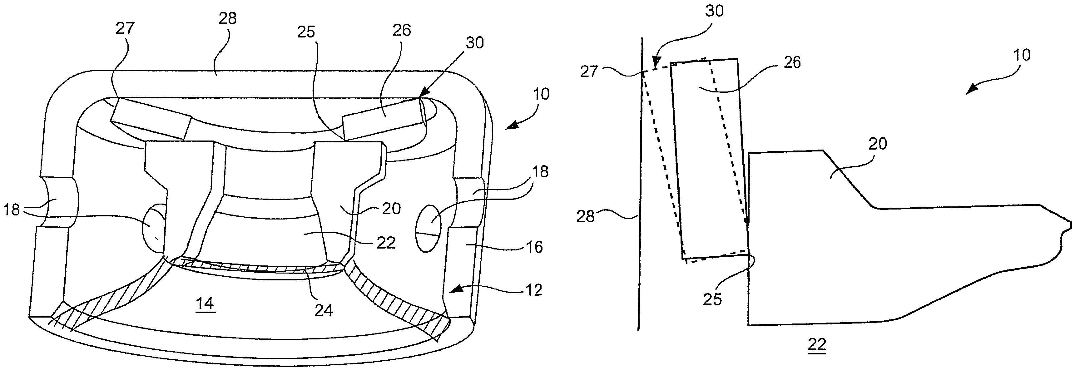
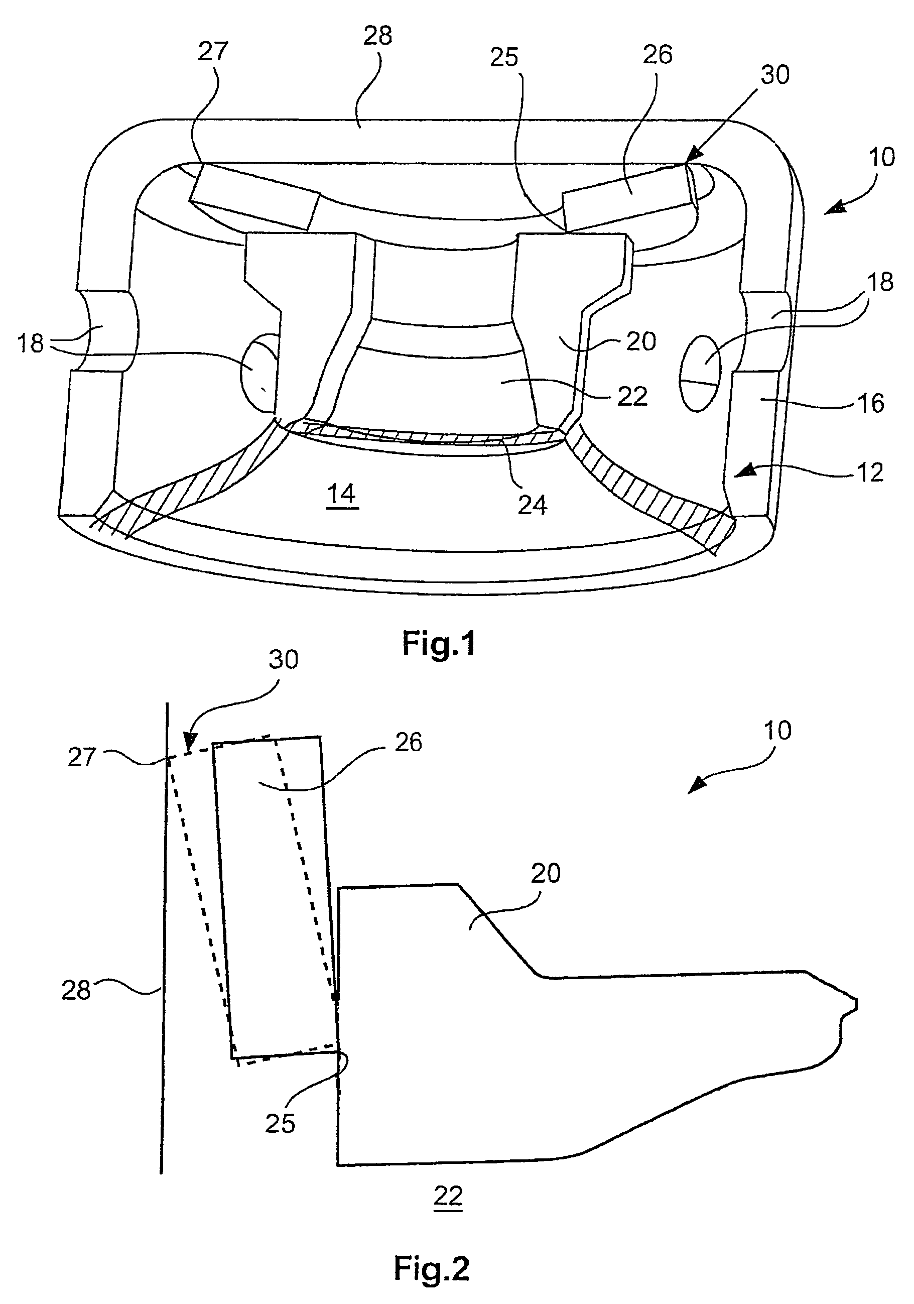
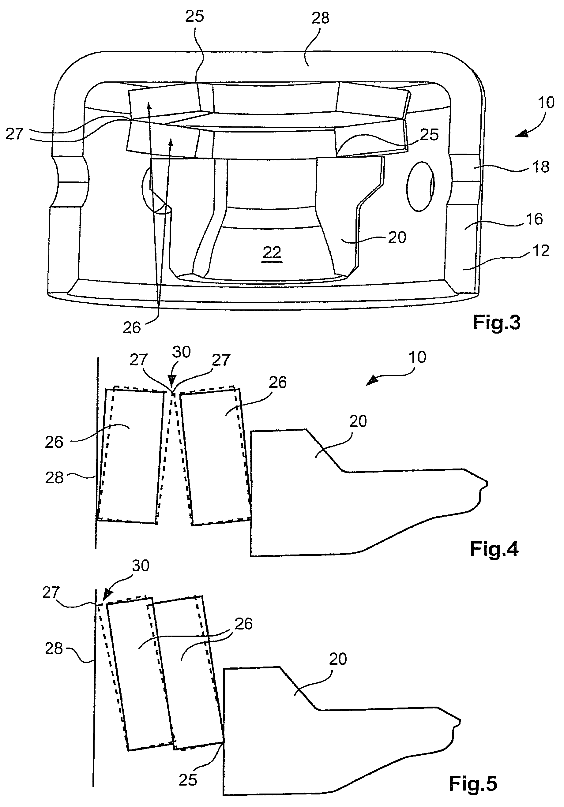
Gas generator
a generator and gas technology, applied in the direction of pedestrian/occupant safety arrangement, transportation and packaging, vehicle safety arrangements, etc., to achieve the effect of improving the deflagration behavior of the propellant, simple design, and increasing the flow cross-section
- Summary
- Abstract
- Description
- Claims
- Application Information
AI Technical Summary
Benefits of technology
Problems solved by technology
Method used
Image
Examples
third embodiment
[0045]FIG. 8 shows the gas generator 10 of the invention, which differs from the embodiments described so far in that the resilient element 26 has the shape of a spherical shell portion or a spherical cap. In its edge portion 33, the resilient element 26 rests against the end-face wall 28 of the diffuser portion 16 on the outer housing 12, whereas the middle portion closes the outflow opening 22 in the normal position shown in FIG. 8. Upon application of compressed gas, the flow cross-section 30 is formed between the edge of the outflow opening 22 and the resilient element 26, in that the same is slightly lifted.
[0046]The gas generator 10 as shown in FIG. 9 merely differs from the one of FIG. 8 in that the resilient element 26 is arranged rotated by 180°, i.e. rests on the end-face wall 28 in its central portion and on the closing element 20 in its edge portion 33. In this aspect, the flow cross-section 30 is formed on the outer edge of the closing element 20.
sixth embodiment
[0047]FIGS. 10 and 11 show a fifth and the gas generator 10 of the invention, in which the component immovable relative to the outer housing, in which a plurality of outflow openings 22 are formed here, is formed by a pot-shaped cap 34 arranged inside the chamber 14. The cap 34 surrounds an opening 36 of the chamber, which in the non-activated condition of the gas generator 10 is closed by a membrane 24. The outflow openings 22 are arranged on the periphery of the cap 34 and in the normal position are closed by a plurality of resilient elements 26, which are disc springs that are arranged one above the other and complement each other to form a bellows-like structure. The outer edges 27 (FIG. 10) and the inner edges 25 (FIG. 11) of the resilient elements 26 rest against the periphery of the cap 34. In the aspect as shown in FIG. 10, the resilient elements 26 are arranged behind the outflow openings 22, but before the membrane 24 with respect to the flow path of the compressed gas. In...
PUM
 Abstract
Description
Claims
Application Information
 - R&D
- Intellectual Property
- Life Sciences
- Materials
- Tech Scout
- Unparalleled Data Quality
- Higher Quality Content
- 60% Fewer Hallucinations
Browse by: Latest US Patents, China's latest patents, Technical Efficacy Thesaurus, Application Domain, Technology Topic, Popular Technical Reports.
© 2025 PatSnap. All rights reserved.Legal|Privacy policy|Modern Slavery Act Transparency Statement|Sitemap|About US| Contact US: help@patsnap.com


