
Method and apparatus for hole diameter profile measurement

a technology of diameter profile and measurement method, which is applied in the direction of mechanical diameter measurement, measurement gauge, instruments, etc., can solve the problems of slow reading ability of users, uncontrolled and unmeasured depth, and difficulty in user effort, so as to reduce the variation of operator-induced measurement

Active Publication Date: 2010-02-23
THE BOEING CO
View PDF19 Cites 8 Cited by
  • Summary
  • Abstract
  • Description
  • Claims
  • Application Information

AI Technical Summary

Benefits of technology

The present invention provides a method and apparatus for measuring the diameter of a hole as a function of depth. The apparatus includes a diametric probe, a foot for positioning the probe, a linear distance probe, and a data acquisition system. The method involves positioning the probe in a plane parallel to the hole and inserting the probe into the hole while recording the diameter and depth data. This allows for quicker and more accurate measurements, reduces operator-induced variation, and provides valuable information on hole quality, material properties, drill wear, and hole shrinkage.

Problems solved by technology

Inspectors currently utilize available hole diameter gages that only report a single diameter in the bore of the hole at an uncontrolled and unmeasured depth in the bore.
The effort challenges the user since the reading ability of the user is slow compared to the rate of change in hole's bore diameter.
Since controlling the rate of descent into the hole is challenging, the true maximum and minimum hole diameters are often missed.
Further, part interfaces are typically ignored since these areas do not represent the true drilling process.
Without a depth reference, it is not possible to exactly judge what depth the gage is at and hence the specified setback requirements cannot be properly met.

Method used


Image

  • Method and apparatus for hole diameter profile measurement
  • Method and apparatus for hole diameter profile measurement
  • Method and apparatus for hole diameter profile measurement

Examples


Embodiment Construction

[0020]In the following description, reference is made to the accompanying drawings which form a part hereof, and which is shown, by way of illustration, several embodiments of the present invention. It is understood that other embodiments may be utilized and structural changes may be made without departing from the scope of the present invention.

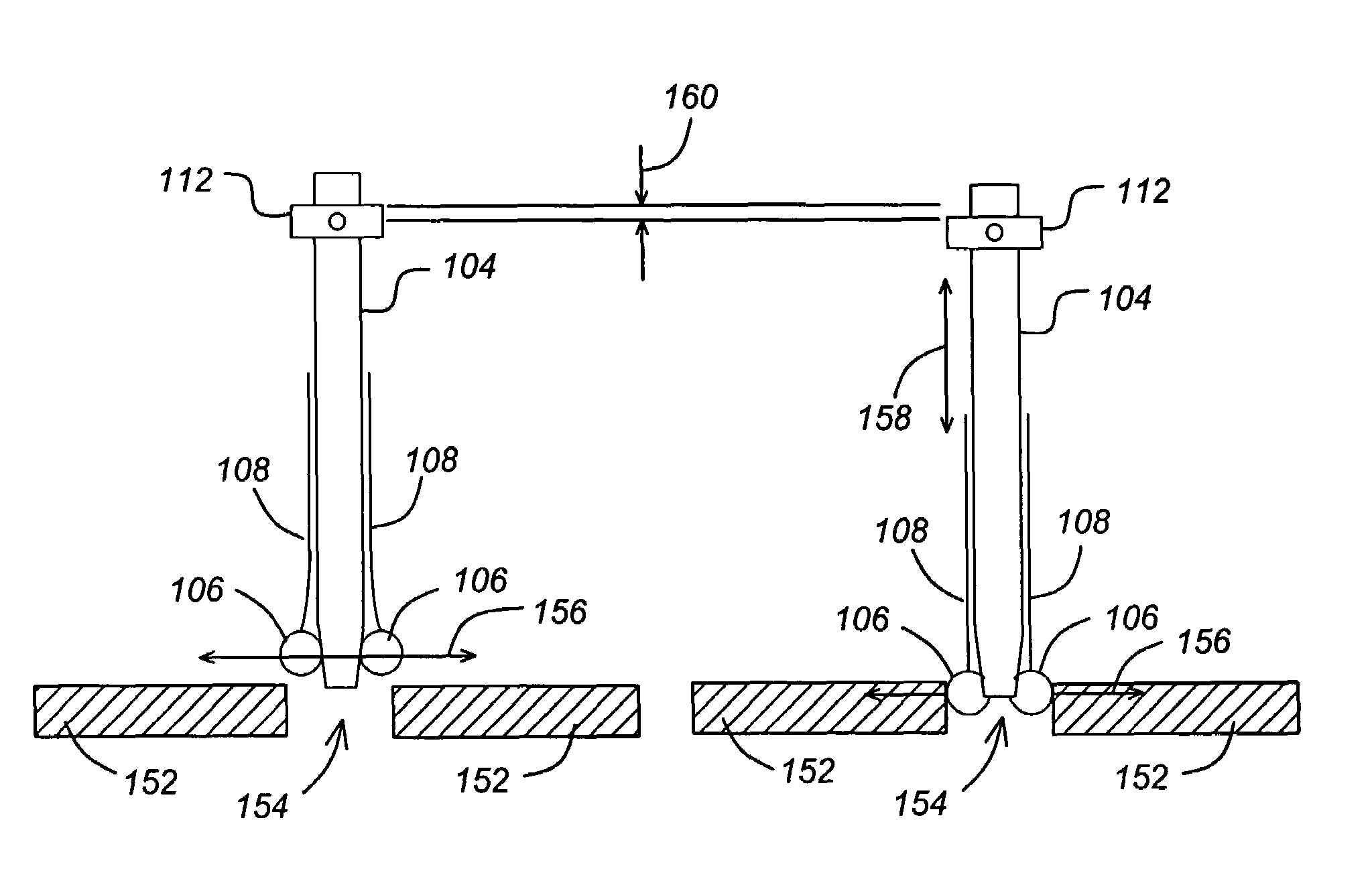
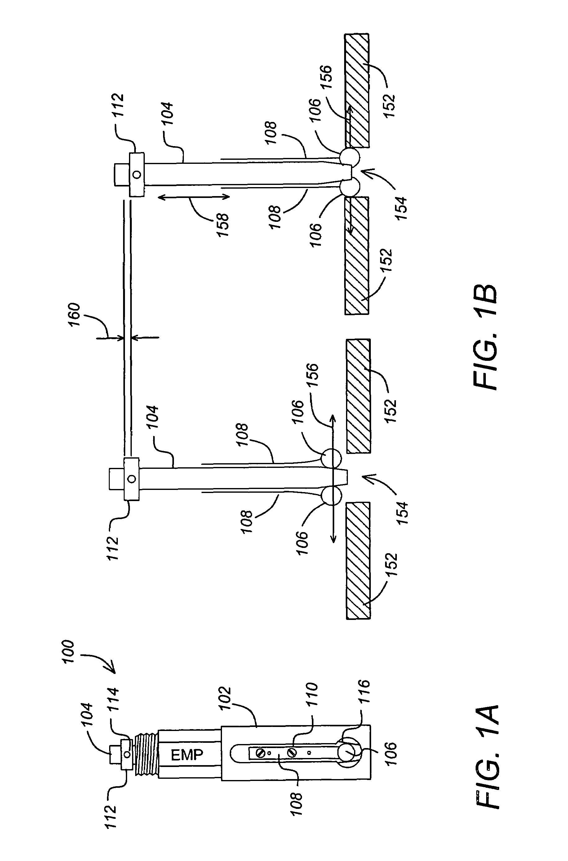
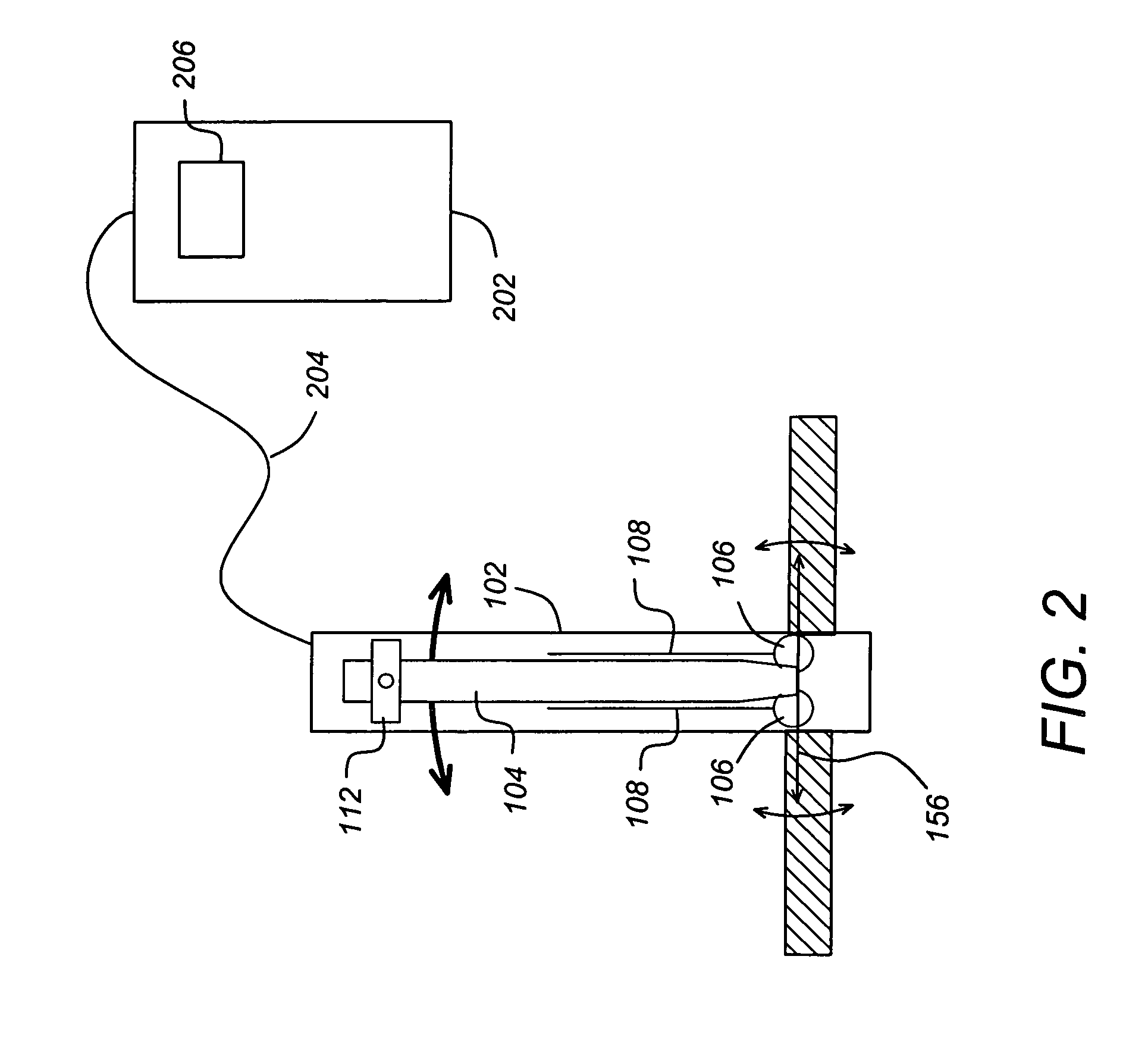
[0021]FIG. 1A is a diagram of one embodiment of a diametric probe 100. This embodiment is also known as a gage plug. The diametric probe 100 comprises an elongated rod 104. The elongated rod 104 has a tapered end and a stop collar 112 affixed by one or more stop collar set screw(s) 114. Contact balls 106 are coupled to the elongated rod 104 via leaf springs 108 and fastening devices such as screws 110. The elongated rods also include a ground surface 116 upon which the contact balls 106 rest.

[0022]FIG. 1B is a diagram illustrating how the diametric probe 100 shown in FIG. 1A can be used to measure the bore diameter of a hole 154 in a surface...


PUM


Abstract

A method and apparatus for measuring the bore diameter of a hole as a function of hole depth is disclosed. In one embodiment, the apparatus comprises a diametric probe, for generating first measured bore diameter data along a diametric probe sensitive axis; a foot, for positioning the diametric probe sensitive axis in a plane parallel to the hole; a linear distance probe, coupled to the diametric probe, for generating first measured depth data describing the depth of the diametric probe sensitive axis within the hole; and a data acquisition system, for recording first measured bore diameter data from the diametric probe and first measured depth data from the linear distance probe of an insertion of the diametric probe into the hole.

Description

BACKGROUND OF THE INVENTION[0001]1. Field of the Invention[0002]The present invention relates generally to systems and methods for measuring hole bore properties, and specifically to a method and apparatus for measuring the bore diameter of as a function of hole depth.[0003]2. Description of the Related Art[0004]Hundreds of thousands of holes are drilled in commercial and military aircraft and spacecraft. Some of these holes are high tolerance holes with a diameter tolerance band of 0.003 inch. Specifications dictate the measurement requirements of these holes, and they typically mandate the measurement of the maximum and minimum diameter at two orientations in the bore of the hole.[0005]Inspectors currently utilize available hole diameter gages that only report a single diameter in the bore of the hole at an uncontrolled and unmeasured depth in the bore. Currently, inspectors are required to insert the gage into the hole and hunt for the minimum and maximum hole diameter readings. ...

Claims


Application Information

Patent Timeline
Patent Type & Authority Patents(United States)
IPC IPC(8): G01B3/00G01B5/00
CPCG01B5/12G01B3/26
Inventor BENNISON, STEPHEN J.HOWARD, BRUCE S.
Owner THE BOEING CO
Learn More