Novel underground non-standard high-pressure flow meter

A flow meter, non-standard technology, applied in the direction of detecting fluid flow by measuring pressure difference, volume/mass flow generated by mechanical effects, etc., can solve the problems of exceeding the measurement range, difficult to guarantee accuracy, and non-measurement, so as to improve the measurement accuracy , Improve measurement accuracy and reduce measurement deviation

Pending Publication Date: 2020-11-10
TANGSHAN CITY FENGRUN DISTRICT ZHANWANG AUTOMATION EQUIP CO LTD
View PDF0 Cites 4 Cited by
  • Summary
  • Abstract
  • Description
  • Claims
  • Application Information

AI Technical Summary

Problems solved by technology

However, the differential pressure flowmeter is only an internal flow meter for surface pipeline applications, which cannot be used for downhole measurement and needs to be redesigned
[0004] If the traditional Venturi flowmeter can be accurately manufactured in accordance with ASME standards, the measurement accuracy can reach 0.5%. However, due to its manufacturing technology problems, the accuracy is difficult to guarantee. As the depth increases, the pressure continues to increase. When the static pressure reaches a certain high value, the common differential pressure transmitters on the market cannot withstand the measurement of the pressure difference, which exceeds the conventional measurement range.
[0005] At the same time, due to the measurement accuracy and measurement error rate of the traditional Venturi flowmeter, when measuring low-flow fluids, there will be a certain deviation in the pressure value measured by itself. When the actual differential pressure value is small, it will fail to measure. Differential pressure, it is impossible to calculate the size of the flow

Method used


Image

  • Novel underground non-standard high-pressure flow meter

Examples


Embodiment

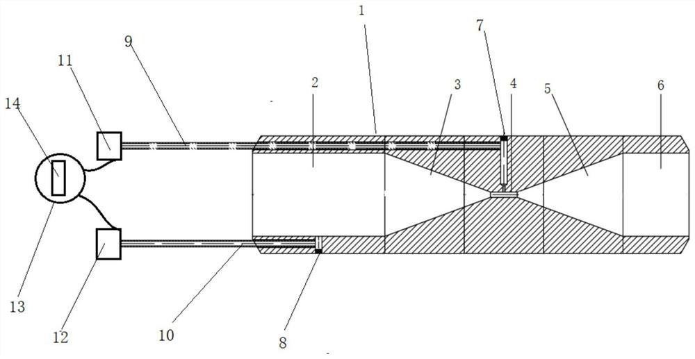
[0024] as attached figure 1 Shown:

[0025] The present invention provides = a new type of downhole non-standard high-pressure flowmeter, including a pipeline body 1, an inlet cylinder section 2, an inlet conical constriction section 3, a throat pipe 4, an outlet conical constriction section 5, an outlet cylinder section 6, a negative pressure take-off Pressure port 7, positive pressure port 8, negative pressure pipe 9, positive pressure pipe 10, first pressure transmitter 11, second pressure transmitter 12, flow display instrument 13, display 14, all The inside of the pipe body 1 is provided with an inlet cylindrical section 2, an inlet conical constriction section 3, a throat 4, an outlet conical constriction section 5, and an outlet cylindrical section 6, and the right side of the inlet cylindrical section 2 is connected to the inlet conical constriction section 3 The right side of the inlet conical constriction section 3 is connected to the throat pipe 4, the right side o...


PUM


Abstract

The invention provides a novel underground non-standard high-pressure flowmeter which comprises a pipeline body; an inlet cylinder section, an inlet conical contraction section, a throat pipe, an outlet conical contraction section and an outlet cylinder section are arranged in the pipeline body, the right side of the inlet cylinder section is connected with the inlet conical contraction section, and the right side of the inlet conical contraction section is connected with the throat pipe. The right side of the throat pipe is connected with the outlet conical contraction section, the outlet conical contraction section is connected with the outlet cylinder section, the negative pressure tapping port is formed in the upper end of the throat pipe, the positive pressure tapping port is connected with the positive pressure tapping pipe; and a first pressure transmitter and a second pressure transmitter are arranged at a left end opening of the negative pressure tapping pipe and a left end opening of the positive pressure tapping pipe respectively. The first pressure transmitter and the second pressure transmitter are respectively connected with a flow display instrument, and a displayeris arranged on the outer surface of the flow display instrument. According to the invention, the measurement precision can be greatly improved, and accurate measurement can be carried out even under the condition of small differential pressure.

Description

technical field [0001] The invention belongs to the technical field of high-pressure flowmeters, and in particular relates to a novel downhole non-standard high-pressure flowmeter. Background technique [0002] Flow rate is one of the most important measurement parameters in production logging. Turbine flow rate is currently the most commonly used flow measurement instrument downhole. Rubber, iron filings, oil, etc. are easy to stick to the turbine, making the turbine flowmeter unable to rotate normally. 85% of the wells cannot complete the measurement of the turbine flow rate. It is difficult to complete the normal flow measurement of these wells, and the success rate of flow logging is low. , Poor production timeliness. In heavy oil wells, flow logging instruments cannot work normally due to adhesion, cannot adapt to downhole working conditions, and are affected by various impurities such as sediment, cuttings, heavy oil, etc., and cannot guarantee flow measurement under ...

Claims


Application Information

Patent Timeline
Patent Type & Authority Applications(China)
IPC IPC(8): G01F1/36G01F1/44G01F1/40
CPCG01F1/36G01F1/40G01F1/44
Inventor 赵菊王文海
Owner TANGSHAN CITY FENGRUN DISTRICT ZHANWANG AUTOMATION EQUIP CO LTD
Why Eureka
Try Eureka