
Thin substrate pitch measurement equipment

a thin substrate and measurement equipment technology, applied in the direction of instruments, specific gravity measurement, counting objects on conveyors, etc., can solve the problems that the distance between wafers cannot be quantitatively measured, and the sag or concaveness of wafers cannot be detected either

Active Publication Date: 2010-02-16
GUDENG EQUIP CO LTD
View PDF9 Cites 11 Cited by
  • Summary
  • Abstract
  • Description
  • Claims
  • Application Information

AI Technical Summary

Benefits of technology

The present invention is a thin substrate pitch measurement equipment that can detect displacement of thin substrates in a container body to prevent damage to other thin substrates or slip-out of thin substrates when the door is opened. It can also measure the vertical distance between thin substrates and alert the operator when the distance is not as expected to prevent cracking or damage to thin substrates during the process. The equipment includes an optical component, a scanning device, and a rotation base that can rotate the container body at least to a certain angle, allowing the optical component to measure the pitch between thin substrates from different positions or angles.

Problems solved by technology

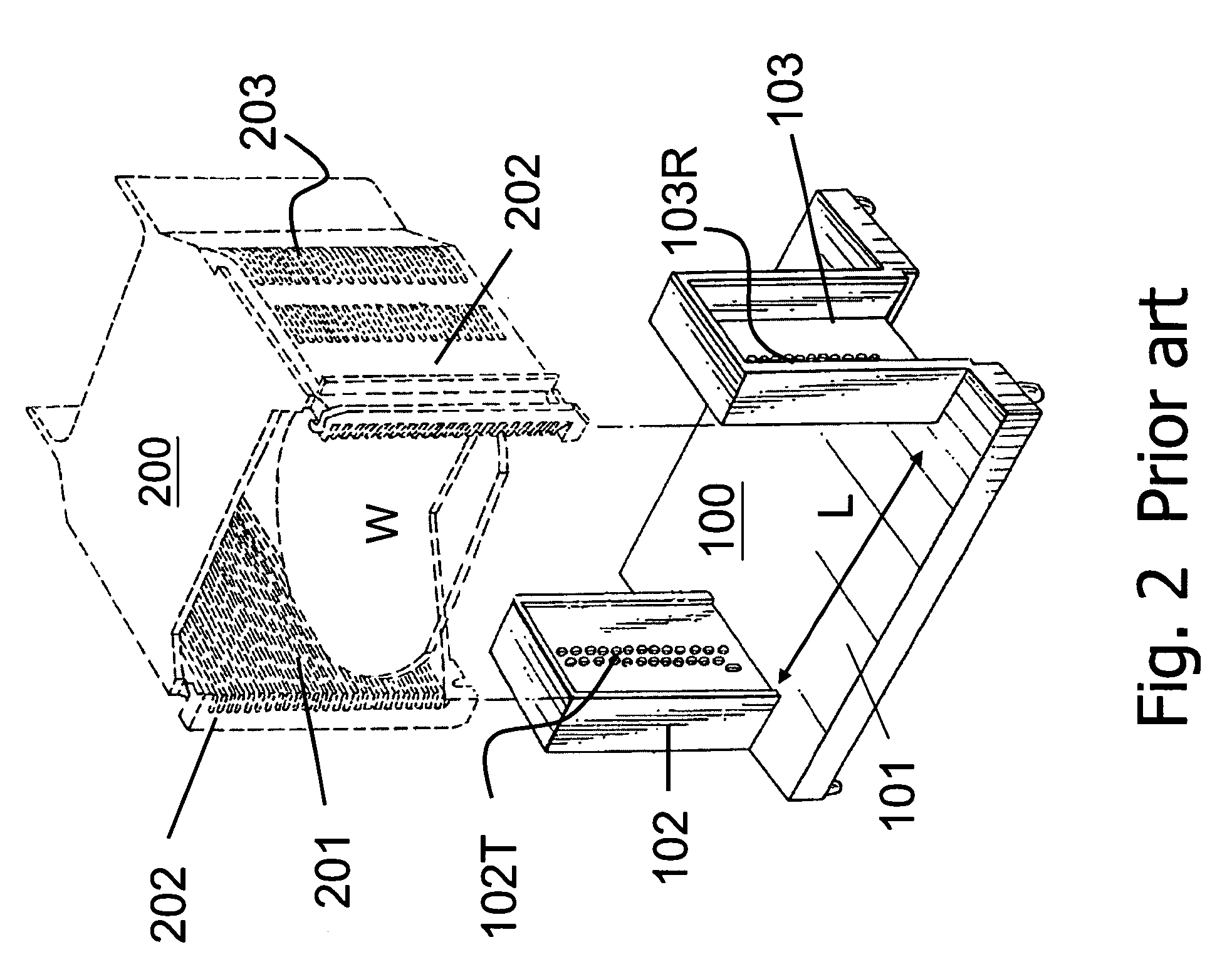
The design of wafer displacement detection system of prior art cannot fulfill the need of front opening unified pod (FOUP) and only the displacement of wafers can be detected; moreover, the distance between wafers cannot be measured quantitatively, and the excessive sag or concavity of wafers cannot be detected either.

Method used


Image

  • Thin substrate pitch measurement equipment
  • Thin substrate pitch measurement equipment
  • Thin substrate pitch measurement equipment

Examples


Embodiment Construction

[0021]In order to disclose the skills applied in, the objectives of, and the effects achieved by the present invention in a more complete and clearer manner, preferred embodiments are herein described below in detail with related drawings disclosed for reference.

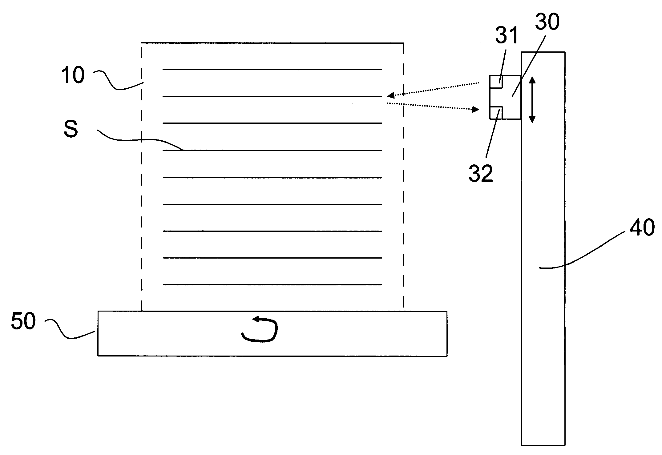
[0022]Referring to FIG. 3, which is a view of a thin substrate pitch measurement equipment of the present invention. The thin substrate pitch measurement equipment includes an optical component 30, a scanning device 40, and a rotation base 50, wherein the optical component 30 is disposed on the scanning device 40 and includes at least a light-transmitter 31 and a light-receiver 32, and the rotation base 50 carries a container body 10 having a plurality of thin substrates S within its interior. The light-transmitter 31 of the aforementioned optical component 30 can be used to transmit a light beam to one of the thin substrates S within the interior of the container body and the light-receiver 32 can be used to detect the ligh...


PUM


Abstract

The present invention provides an equipment for measuring the vertical distance or pitch between a plurality of thin substrates inside a container body, including an optical component to transmit a light beam to a thin substrate in the container body and receive light beam reflected from the thin substrate, a scanning device to drive the optical component to move along vertical direction of the thin substrates for measuring the vertical distance or pitch between the plurality of thin substrates in the container body, and a rotation base to carry and rotate the container body to a plurality of angles for the plurality of thin substrates inside the container body to be measured from different angular positions.

Description

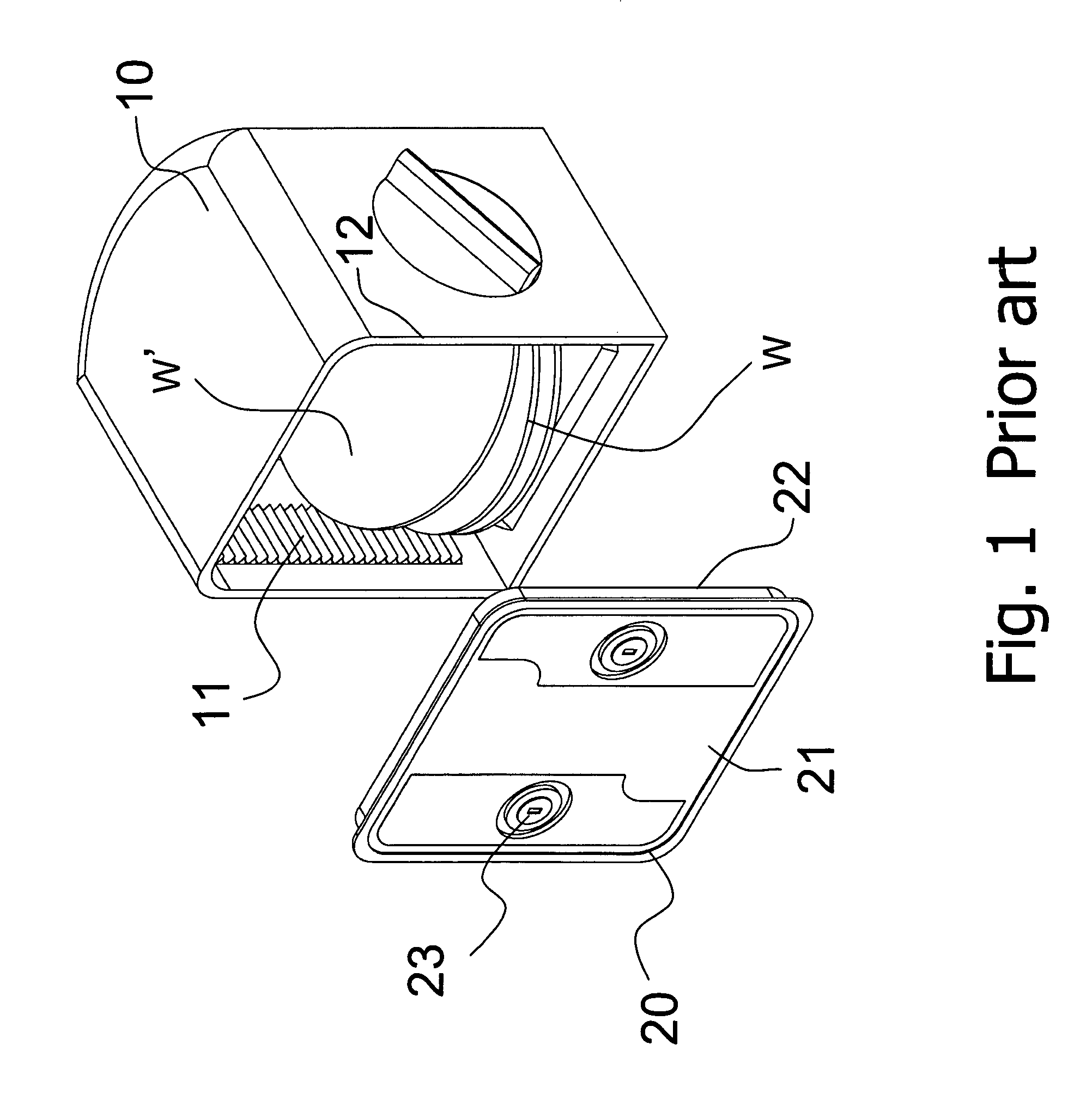
BACKGROUND OF THE INVENTION[0001]1. Field of the Invention[0002]The present field of the invention is related to a measurement equipment for measuring pitch between thin substrates, and more particularly, to a measurement equipment for measuring pitch between thin substrates placed in the interior of container body from a plurality of different angles or different positions with the container body being rotated.[0003]2. Description of the Prior Art[0004]The semiconductor wafers are transferred to different stations to apply the various processes in the required equipments. A sealed container is provided for automatic transfer to prevent the pollution from occurring during transferring process. FIG. 1 shows the view of wafer container of the conventional prior art. The wafer container is a front opening unified pod (FOUP) which includes a container body 10 and a door 20. The container body 10 is disposed with a plurality of slots 11 for horizontally supporting a plurality of wafers W...

Claims


Application Information

Patent Timeline
Patent Type & Authority Patents(United States)
IPC IPC(8): G08B21/00
CPCH01L21/67265
Inventor LU, PAO-YI
Owner GUDENG EQUIP CO LTD
Learn More