Printer
a printing machine and printing plate technology, applied in the field of printing machines, can solve problems such as difficulty in appropriately printing images, and achieve the effect of reducing the number of sensors
- Summary
- Abstract
- Description
- Claims
- Application Information
AI Technical Summary
Benefits of technology
Problems solved by technology
Method used
Image
Examples
embodiments
[Physical Configuration of the Printer]
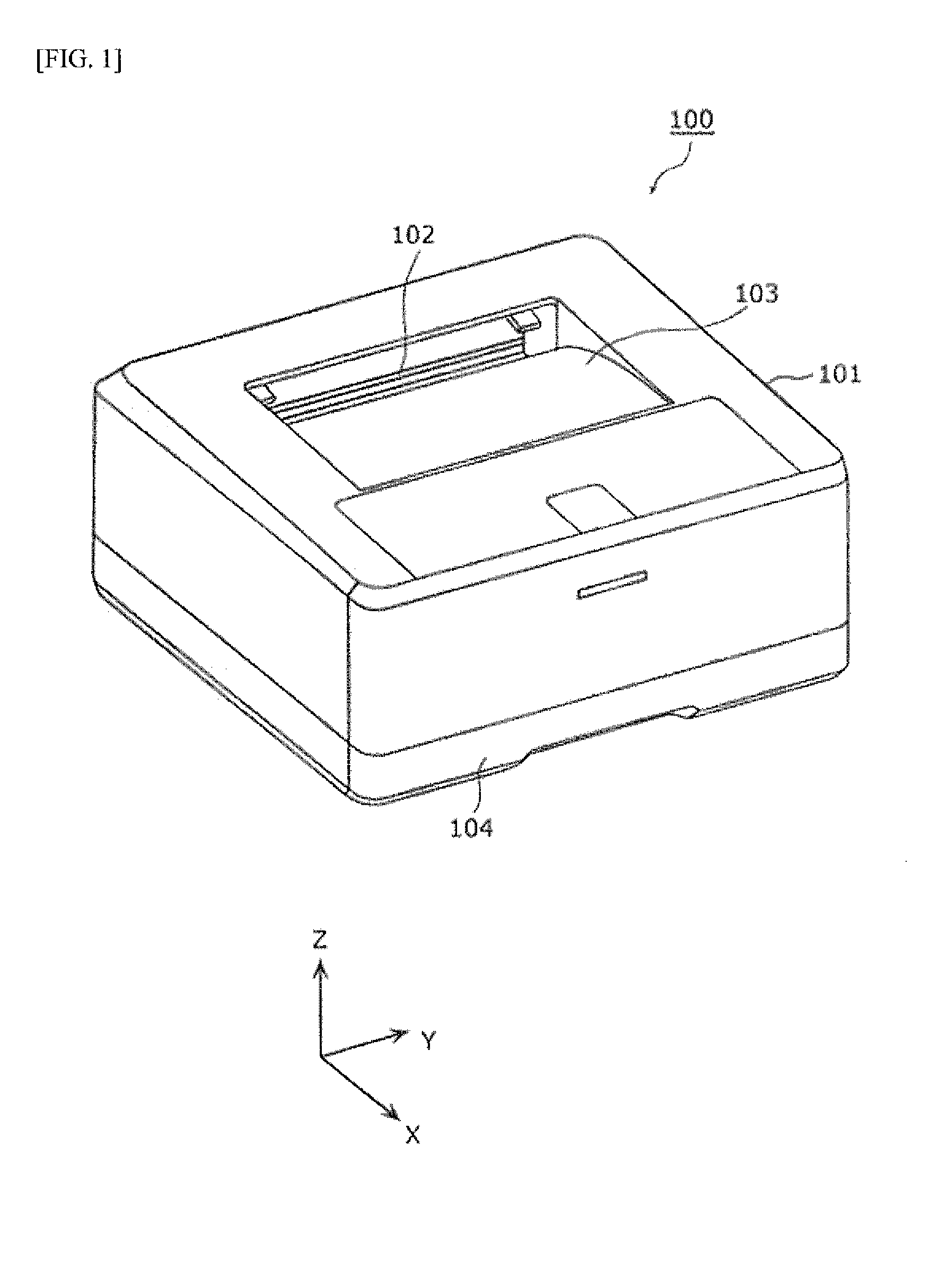
[0041]A physical configuration of a printer 100 in accordance with one or more embodiments of the present invention is described first. FIG. 1 is a perspective view showing an exterior view of the printer 100 according to one or more embodiments of the present invention.
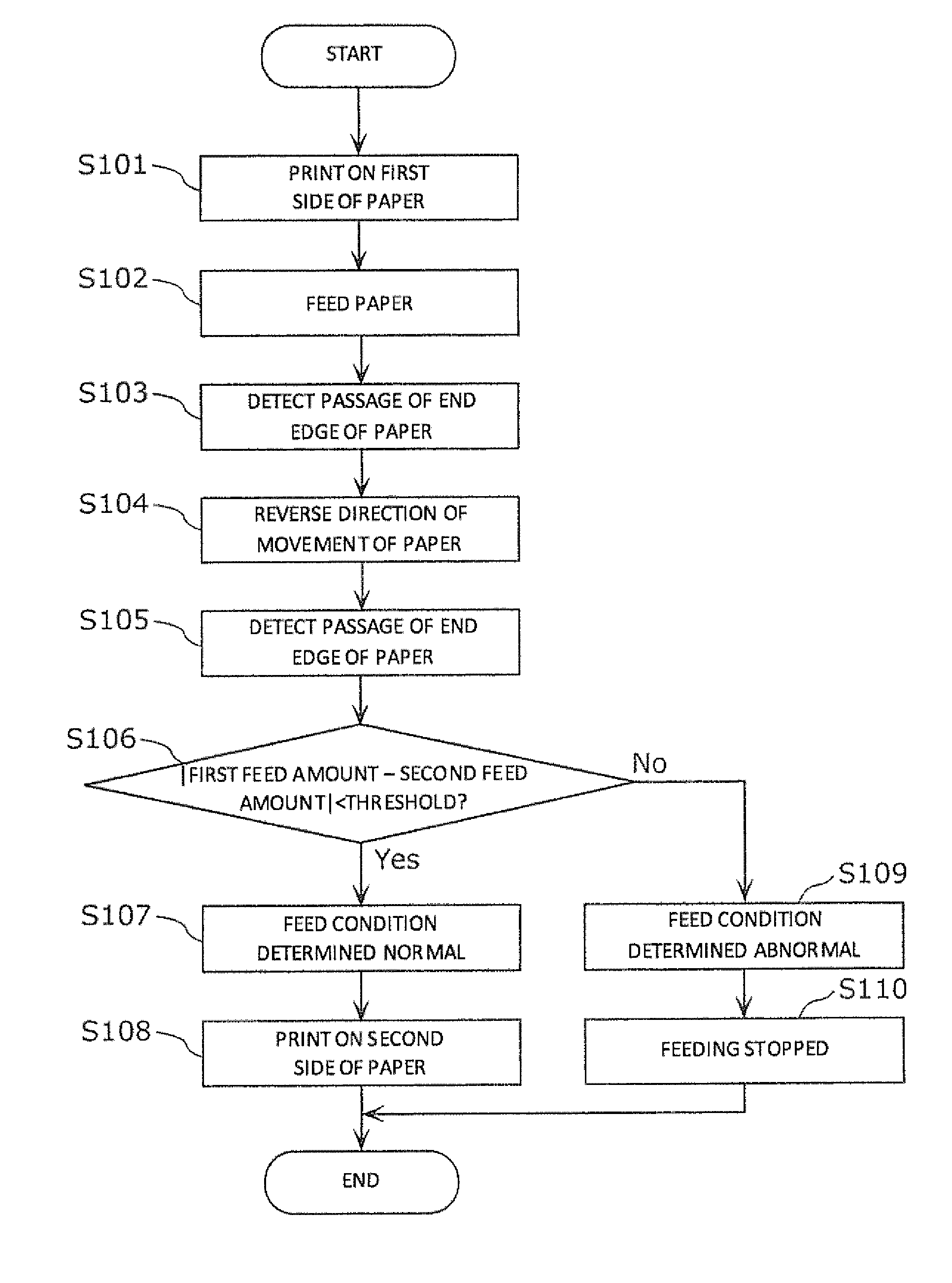
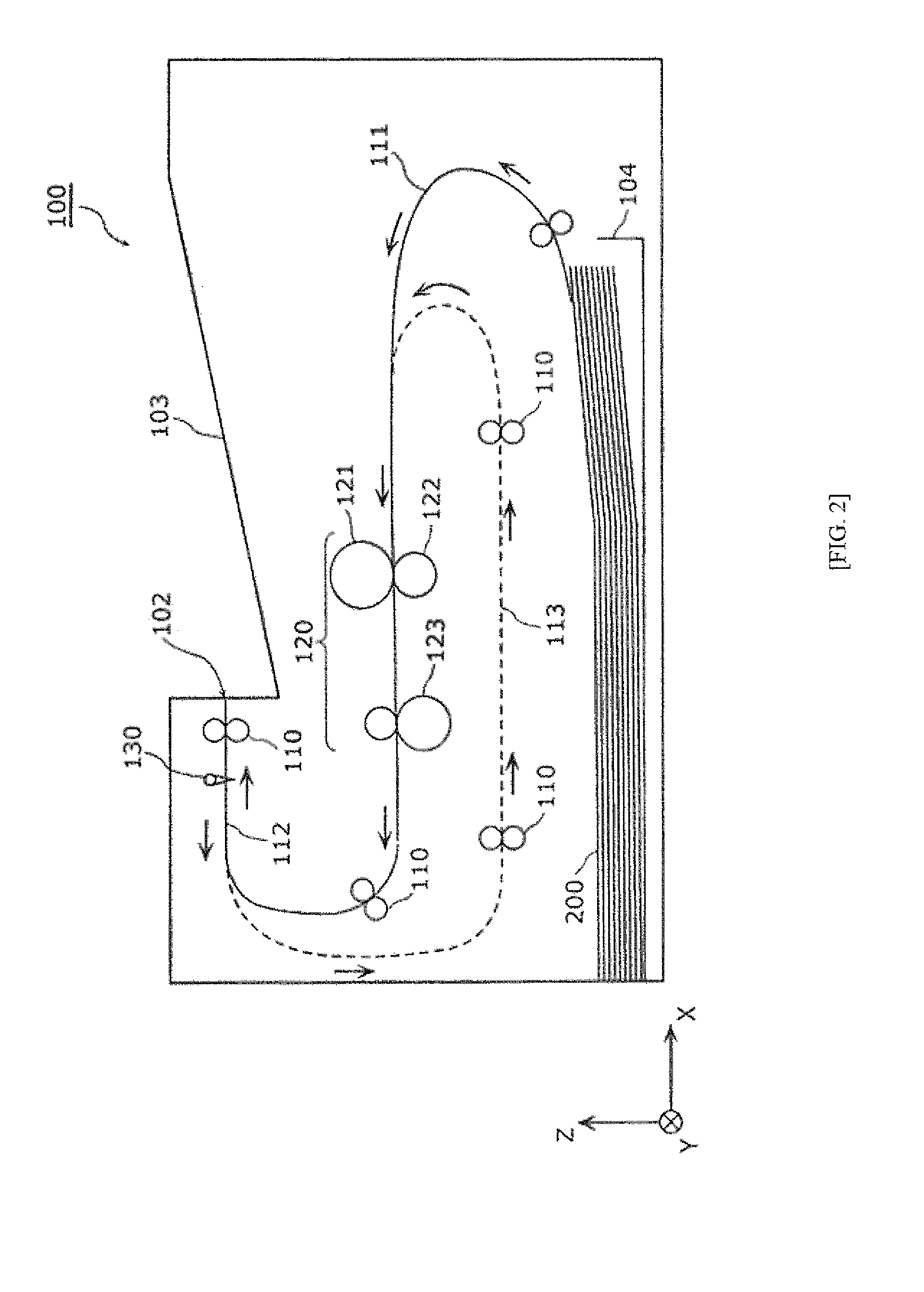
[0042]The printer 100 performs double-sided printing by turning over the paper by feeding the paper in a reverse direction by reversing the direction of movement while the paper is fed in the forward direction along the discharge route for discharging the printed paper. In one or more embodiments of the present invention, the printer 100 is a laser printer.
[0043]As illustrated in FIG. 1, the printer 100 is equipped with a chassis 101, a discharge port 102 formed on the chassis 101, a catch tray 103, and a paper cassette 104.
[0044]The discharge port 102 is an aperture through which printed paper is discharged from the interior of the chassis 101. When double-sided printing is per...
modification 1
(Modification 1)
[0094]Next, a modification 1 of the embodiments is described. In one or more embodiments of the present modification, the number of levers contained in the displacement member is different than in the above embodiments. The displacement member is described below centered on points that differ from the above embodiments.
[0095]FIG. 11 is a perspective view of a displacement member 130A of the printer according to one or more embodiments of the modification 1. In FIG. 11, identical symbols are used for configuration elements identical to FIG. 3, and their description is omitted.
[0096]The displacement member 130A has two levers 132A. The two levers 132A contain a first lever 133 and a second lever 134. In other words, in the displacement member 130A of the present modification, the third lever 135 contained in the displacement member 130 of the above embodiments is missing. However, because the first lever 133 and the second lever 134 are provided, the displacement membe...
modification 2
(Modification 2)
[0098]A modification 2 of the embodiments is described next. In one or more embodiments of the present modification, the shape and number of the lever contained in the displacement member is different than the above embodiments. The displacement member is described below centered on points that differ from the above embodiments.
[0099]FIG. 12 is a perspective view of the displacement member 130B of the printer according to one or more embodiments of the modification 2. In FIG. 12, identical symbols are used for configuration elements identical to FIG. 3, and their description is omitted.
[0100]The displacement member 130B is equipped with a shaft 131 and a lever 132B. The lever 132B is provided longitudinally over the shaft 131, and is a plate-shaped member disposed so it protrudes facing the route surface 112a of the discharge route 112. Even when the lever 132B is shaped in this manner, the displacement member 130B can accurately detect the passage of the paper 200.
[...
PUM
 Abstract
Description
Claims
Application Information
 - R&D
- Intellectual Property
- Life Sciences
- Materials
- Tech Scout
- Unparalleled Data Quality
- Higher Quality Content
- 60% Fewer Hallucinations
Browse by: Latest US Patents, China's latest patents, Technical Efficacy Thesaurus, Application Domain, Technology Topic, Popular Technical Reports.
© 2025 PatSnap. All rights reserved.Legal|Privacy policy|Modern Slavery Act Transparency Statement|Sitemap|About US| Contact US: help@patsnap.com


