Displacement detecting device with controlled heat generation
a technology of displacement detection and heat generation, which is applied in the direction of measurement devices, instruments, optics, etc., can solve the problems of limited mechanical response frequency of upward/downward movement of the objective lens, decrease in the resolution of measurement during expansion of the measurement range, and low sensitivity, so as to achieve the effect of widening the use condition and controlling the heat generated in us
- Summary
- Abstract
- Description
- Claims
- Application Information
AI Technical Summary
Benefits of technology
Problems solved by technology
Method used
Image
Examples
first embodiment
1. First Embodiment of Displacement Detecting Device
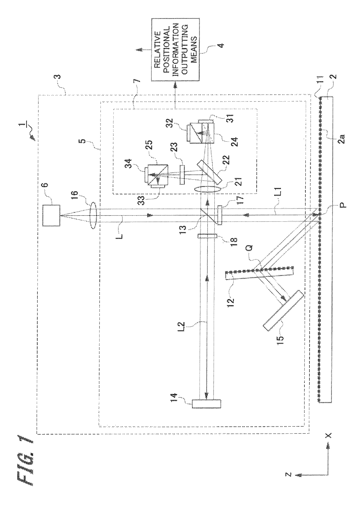
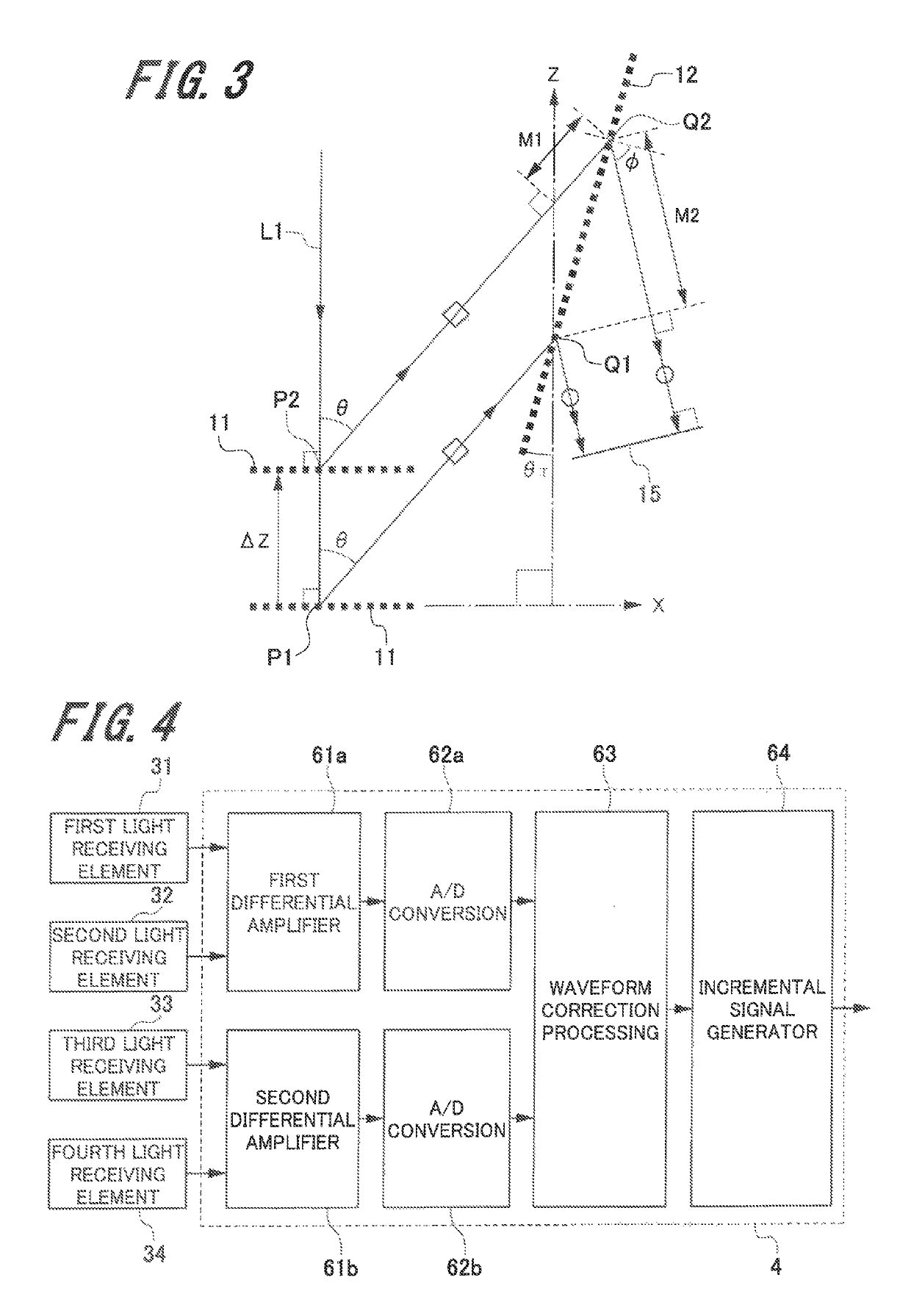
[0052]First, the first embodiment (hereinafter, referred to as “present embodiment”) of the displacement detecting device of the present invention will be described with reference to FIG. 1 to FIG. 3.
[0053]1-1. Configuration Example of Displacement Detecting Device
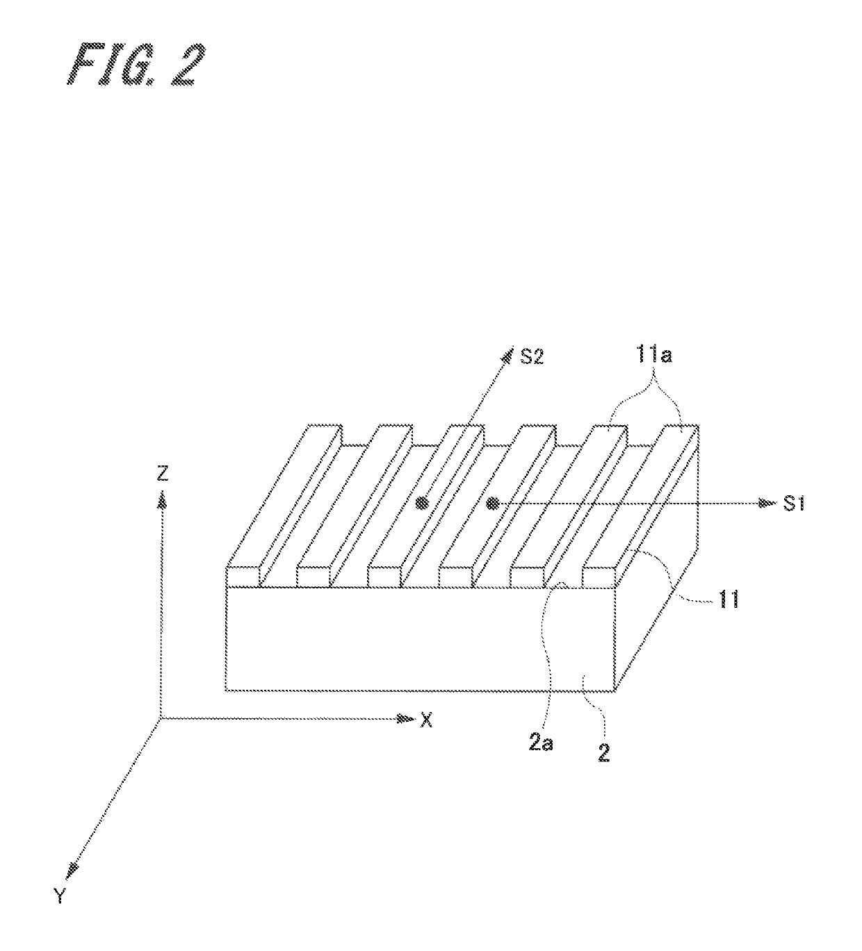
[0054]FIG. 1 is a schematic configuration view illustrating a configuration of the displacement detecting device. FIG. 2 is a perspective view illustrating a measured member in which a first diffraction grating is provided in the displacement detecting device.
[0055]A displacement detecting device 1 of the present embodiment is a displacement detecting device that detects displacement (movement amount) of when at least one of a head and a measured member is moved.
[0056]As illustrated in FIG. 1, the displacement detecting device 1 includes a first diffraction grating 11 provided on a measured surface 2a of a measured member 2, a head 3, and a relative positional information...
second embodiment
2. Second Embodiment
[0156]Next, a displacement detecting device according to the second embodiment will be described with reference to FIG. 6 and FIG. 7.
[0157]FIG. 6 is a schematic configuration view illustrating a configuration of the displacement detecting device according to the second embodiment, and FIG. 7 is a block diagram illustrating a relative positional information outputting means in the displacement detecting device according to the second embodiment.
[0158]A displacement detecting device 101 according to the second embodiment is a displacement detecting device that can output two-dimensional displacement information in a first direction X and a third direction Z. Thus, here, the same sign is assigned to a common part with the displacement detecting device 1 according to the first embodiment, and an overlapped description is omitted.
[0159]As illustrated in FIG. 6, a displacement detecting device 101 includes a measured member 2 in which a first diffraction grating 111 is...
third embodiment
3. Third Embodiment
[0177]Next, a displacement detecting device according to the third embodiment will be described with reference to FIG. 8 to FIG. 12B.
[0178]FIG. 8 is a schematic configuration view illustrating a configuration of the displacement detecting device according to the third embodiment. FIG. 9 is a schematic configuration view illustrating a configuration of a first displacement detecting unit and a second displacement detecting unit in the displacement detecting device according to the third embodiment. FIG. 10 is a schematic view illustrating a configuration of a third displacement detecting unit and a fourth displacement detecting unit in the displacement detecting device according to the third embodiment. FIG. 11 is a block diagram illustrating a relative positional information outputting means in the displacement detecting device according to the third embodiment. FIG. 12A and FIG. 12B are views illustrating a first diffraction grating in the displacement detecting ...
PUM
 Abstract
Description
Claims
Application Information
 - R&D
- Intellectual Property
- Life Sciences
- Materials
- Tech Scout
- Unparalleled Data Quality
- Higher Quality Content
- 60% Fewer Hallucinations
Browse by: Latest US Patents, China's latest patents, Technical Efficacy Thesaurus, Application Domain, Technology Topic, Popular Technical Reports.
© 2025 PatSnap. All rights reserved.Legal|Privacy policy|Modern Slavery Act Transparency Statement|Sitemap|About US| Contact US: help@patsnap.com


