
Jetting timing determining method, liquid-droplet jetting method and ink-jet printer

a timing determination and liquid droplet technology, applied in printing, other printing apparatus, etc., can solve the problems of non-uniform image formed by ink jetting, and achieve the effect of improving the quality of the obtained imag

Active Publication Date: 2010-02-16
BROTHER KOGYO KK
View PDF6 Cites 0 Cited by
  • Summary
  • Abstract
  • Description
  • Claims
  • Application Information

AI Technical Summary

Benefits of technology

The present invention provides a method for determining the optimal timing for jetting ink droplets from a liquid-droplet jetting head with multiple nozzles. This method addresses the issue of varying jetting speeds when ink is jetted from different nozzles simultaneously. By determining the delay time that results in the optimal image quality for each nozzle group, the method ensures that the ink droplets are jetted in a way that minimizes cross-talk and improves reproducibility of the printed image. The method can be easily implemented and can be used with different types of ink and nozzle groups.

Problems solved by technology

When the ink jetting characteristics are varied among the nozzles upon the concurrent jetting due to the cross talk, there is a fear that an image, formed by the ink jetting, becomes non-uniform.

Method used


Image

  • Jetting timing determining method, liquid-droplet jetting method and ink-jet printer
  • Jetting timing determining method, liquid-droplet jetting method and ink-jet printer
  • Jetting timing determining method, liquid-droplet jetting method and ink-jet printer

Examples


Embodiment Construction

[0052]In the following, a preferred embodiment of the present invention will be explained. First, an explanation will be given about an ink-jet head which is an object of the jetting-timing determining method of the present invention, and a printer provided with the ink-jet head. Next, a preferred embodiment according to the jetting-timing determining method will be explained.

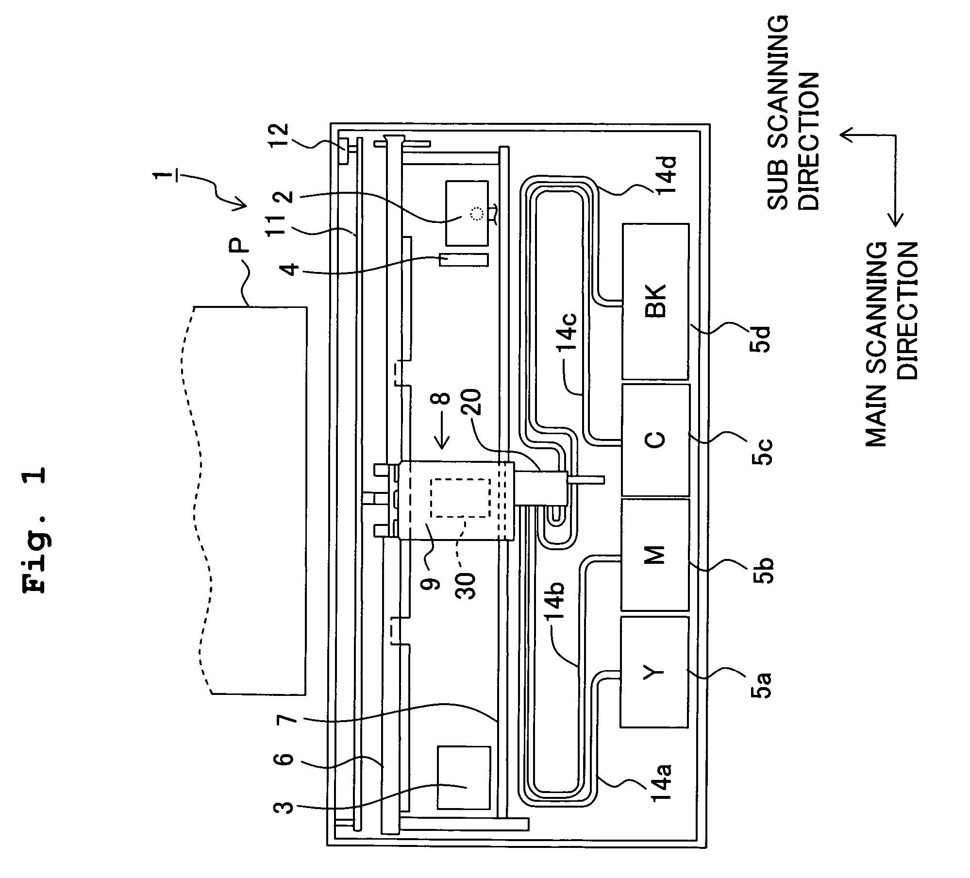
[0053]FIG. 1 shows an example of the ink-jet printer 1 (printer 1) as an object of the jetting-timing determining method of the present invention. FIG. 1 shows the inside of the printer 1 as viewed from above.

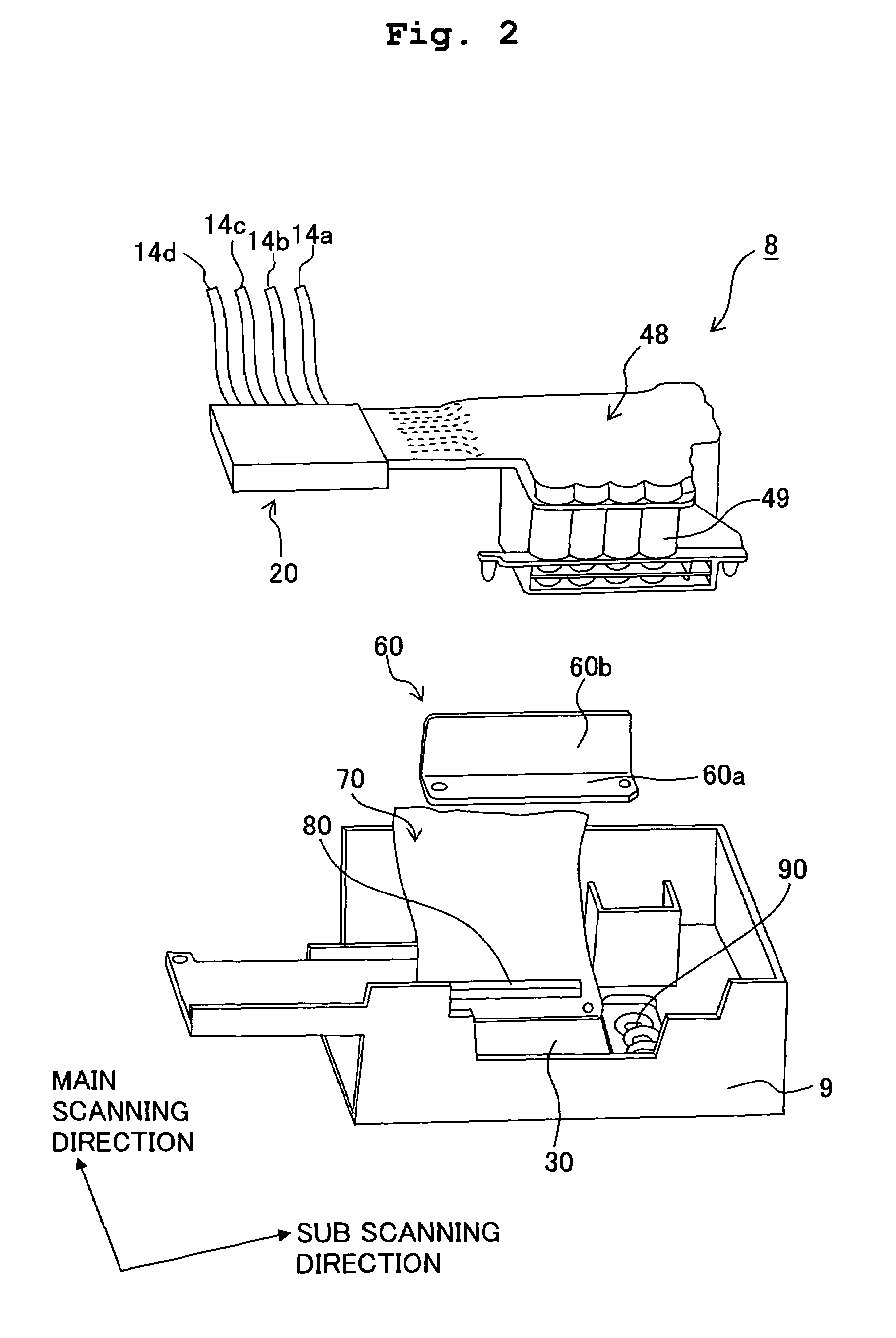
[0054]In the inside of the printer 1, two guide shafts 6 and 7 are provided. A head unit 8, which serves as a carriage, is arranged in the guide shafts 6 and 7 to be reciprocapable along a main scanning direction (left and right direction in FIG. 1). The head unit 8 has a head holder 9 which is formed of a synthetic resin material. The head holder 9 holds an ink-jet head 30 which performs printing by disch...


PUM


Abstract

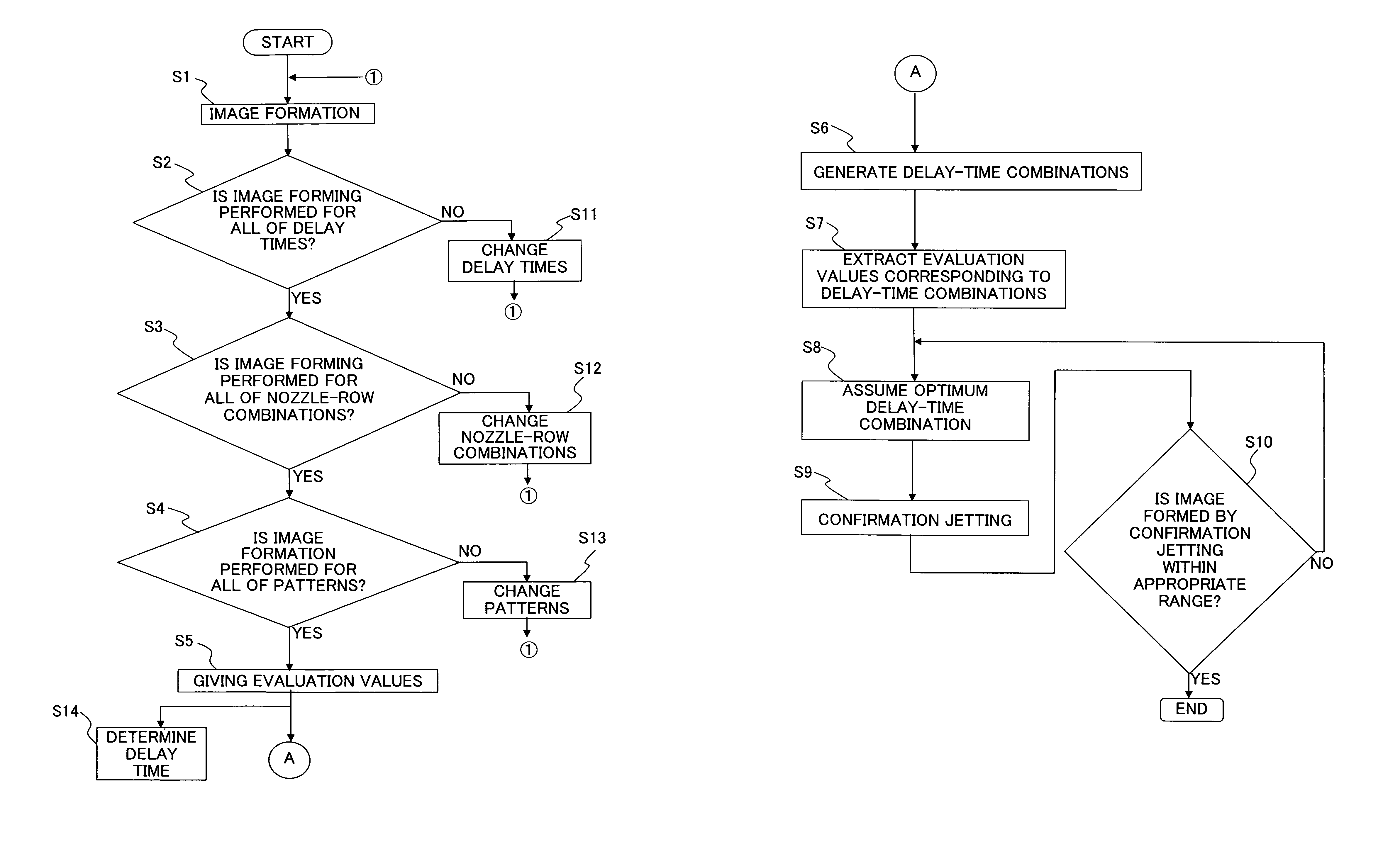
In a liquid-droplet jetting apparatus such as an ink-jet head having a plurality of nozzle rows formed therein, an ink is jetted from one of the nozzle rows and the ink is jetted from another nozzle row concurrently while changing delay times by each of which a jetting timing for the nozzle row is delayed with respect to a jetting timing for the another nozzle row. Then, an optimum image is determined among images formed by the ink jetted from these two nozzle rows, and a delay time in the jetting timings is extracted, among the delay times, which correspond to the optimum image. By determining the delay time in the nozzle rows in such a manner, the variation in jetting characteristics is small in the nozzle rows, thereby realizing satisfactory reproducibility of image.

Description

CROSS REFERENCE TO RELATED APPLICATION[0001]The present application claims priority from Japanese Patent Application No. 2005-341345 filed on Nov. 28, 2005, the disclosure of which is incorporated herein by reference in its entirety.BACKGROUND OF THE INVENTION[0002]1. Field of the Invention[0003]The present invention relates to a jetting timing determining method for determining a timing at which a liquid such as an ink is jetted from a liquid-droplet jetting head such as an ink-jet head, a liquid-droplet jetting method, and an ink-jet printer which jets the ink at a predetermined timing.[0004]2. Description of the Related Art[0005]An example of a technique to utilize an ink-jet head, in which a plurality of nozzles for jetting (discharging) an ink is formed, is described in Japanese Patent Application Laid-open No. 2005-271543.[0006]When the ink is jetted from an ink-jet head as described in Japanese Patent Application Laid-open No. 2005-271543, a difference sometimes arises in ink...

Claims


Application Information

Patent Timeline
Patent Type & Authority Patents(United States)
IPC IPC(8): B41J29/393B41J29/38
CPCB41J2/04573B41J2/0458B41J2/17509B41J2/17513B41J2/2128B41J29/393
Inventor IRIGUCHI, AKIRA
Owner BROTHER KOGYO KK
Learn More